 网站地图
网站地图


-
植入心血管支架作为心脏介入手术的主要治疗手段,工业上成熟的产品为球囊式支架。目前球囊式支架大多数采用激光切割工艺,这种加工方法生产效率高且成本低。但由于激光切割属于“热”加工,在切缝侧面形成的热影响区(heat affected zone, HAZ)及重铸层会直接影响材料的强度和疲劳寿命[1-4]。近年来国内外诸多学者致力于研究激光加工血管支架重铸层及热影响区的分布规律,得到了影响重铸层及热影响区的关键因素:脉冲宽度、脉冲频率、脉冲功率及切割速度[5-10]。光纤激光加工是近十几年发展起来的一种新型工艺方法,与Nd:YAG相比,激光光束质量更优、加工精度更高,从而逐渐应用于心血管支架制造行业[11-21]。
为了探究光纤激光工艺参量(激光脉冲宽度、脉冲频率、激光功率、切割速度)对心血管支架重铸层和热影响区形成机理及变化规律的影响,本文中从激光切割过程中材料内部产生的熔体区及受热区入手,分析了在关键工艺参量下重铸层及热影响区的形成机理及变化趋势,为后续的正交实验及电解抛光提供了数据依据。
-
如图 1a所示,本次切割心血管支架选用的激光切割设备的型号为TLS-HT1100,其激光参量如表 1所示。

Figure 1. Laser equipment and cardiovascular stent
Table 1. The range of laser process parameters
pulse power pulse width pulse frequency cutting speed 50W~150W 1μs~10ms 1Hz~10000Hz 0mm/s~10mm/s 该支架激光切割机中光纤激光器波长为1064nm,光束质量因子M2=1.05,光斑聚焦直径为20μm,并采用与光纤激光器同轴、气压为0.3MPa的氩气作为保护气体,同时向管内注入冷却水实现湿式切割。在切割过程中工控机控制x轴平移和y轴转动使工件相对于光束移动完成切割,切割后316L心血管支架长度为13mm,外径为2.6mm,管厚为0.2mm(如图 1b所示)。
-
采用Quanta 250型号的扫描电子显微镜(scanning electron microscope, SEM)对切割后的心血管支架的热影响区及重铸层进行检测、数据处理及分析。
-
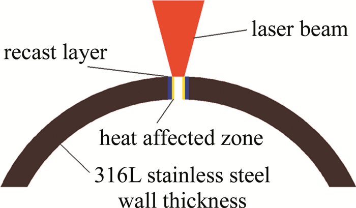
根据激光功率密度的计算公式可知,该设备的功率密度级数为107W/cm2,因此切割支架主要方式为融化去除。在加工过程中材料会形成熔体区及受热区,其具体形成机理如图 2所示。当激光光斑射向材料表面时,材料吸收激光热量而达到融化温度形成熔体区,同时熔体区将一部分热量继续传递给材料内部形成受热区。熔体区主要分布在光斑内部,而受热区则分布在光斑外部,当激光停止作用时熔体区的一部分在力和热的作用下排出,剩余部分冷却形成重铸层。此外,受热区冷却后则形成与母相不同的晶体结构即热影响区。

Figure 2. Formation of HAZ and recast layer during processing
-
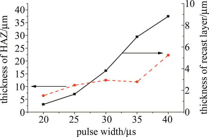
图 3为不同脉冲宽度下支架重铸层及热影响区的变化规律。从图 3中可以看出, 支架重铸层及热影响区的厚度随脉冲宽度的增大而增大,从熔体区变化情况来看,随着脉宽增大,激光峰值功率密度降低,熔体获得的反冲动量减小使熔体的流速变慢,残留在切缝侧面的熔体质量及体积增多,导致重铸层厚度增大;另一方面当脉冲宽度增加时,激光占空比增大,光斑与材料的接触时间增长,导致光斑热辐射强度增大,熔体区向受热区传递的热量增多,增大了热影响区的厚度。当脉冲宽度在20μs~40μs之间变化时,重铸层厚度变化范围为3.0μm~37.4μm;热影响区厚度变化范围为6.4μm~22.2μm。

Figure 3. Thickness of recasting layer and HAZ varying with pulse width
-
图 4为不同脉冲频率下支架重铸层及热影响区的变化规律。可以看出, 脉冲频率在5000Hz~10000Hz之间变化时无明显重铸层。这是因为一方面脉冲频率增加导致峰值功率密度降低,熔体反冲动量及吸收的热量减小,导致熔体的流速变慢,残余在切缝表面的熔体增多使重铸层的厚度增大;另一方面随着脉冲频率的增大,单位时间内激光冲击材料的次数增多、熔体强制流动的动量增强,两者作用抵消导致脉冲频率变化时无明显的重铸层厚度。当脉冲频率小于7000Hz时,未检测到明显的热影响区。这是由于脉冲频率与激光占空比成正比,当激光占空比过低时热量被熔体完全吸收,因而无法继续传递至材料内部,此时无明显的热影响区。随着脉冲频率的增大,激光占空比增大,光斑的热辐射强度增大,此时熔体不能全部吸收来自激光的热量,导致一部分热量通过熔体转移至受热区,由于熔体区达到融化状态所需的热量是一定的,占空比越大导致熔体区向受热区传递的热量越多,形成的热影响区越厚。当脉冲频率从5000Hz~10000Hz变化时,热影响区变化范围为0.2μm~6.4μm,图 5为脉冲频率9000Hz时, SEM检测支架热影响区的分布情况。
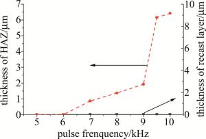
Figure 4. Thickness of recasting layer and HAZ varying with pulse frequencies

Figure 5. The distribution of stent HAZ with 9000Hz pulse repetition frequency
-
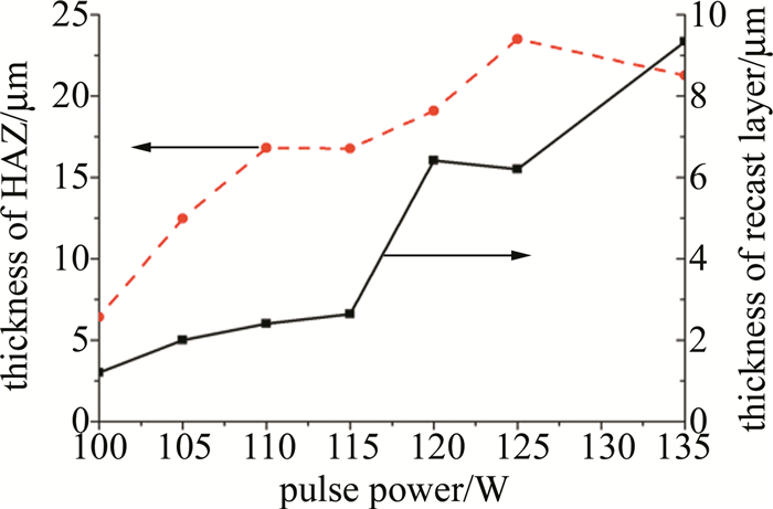
图 6为不同激光功率对支架重铸层及热影响区影响规律。从图 6中看出,重铸层厚度的总体趋势是随脉冲功率增大而增大。这是由于当脉冲功率增大时,激光能量密度增大,导致光斑对材料表面作用强度增大,从而导致重铸层厚度逐渐增大, 而热影响区厚度的变化趋势为先增大后减小。一方面是因为当激光功率升高时,激光能量密度增大,光斑内达到316L医用不锈钢阈值的面积增大,切缝的宽度也随之增大;另一方面当激光功率增大时,在激光光斑面积恒定的情况下,光斑功率密度增大导致热辐射强度增大,熔体区向受热区传递的热量增多,导致热影响区厚度也随之增大。因此,在加工过程中,提高激光功率会导致受热区厚度增大,同时也会导致切缝增大,两者共同作用导致热影响区厚度发生变化。当功率在125W以下时,切缝的增大程度低于受热区增厚程度,热影响区厚度逐渐增大;当激光功率大于125W时,切缝的增大程度大于受热区增厚程度,热影响区厚度逐渐减小。当脉冲功率在100W~135W之间变化时,重铸层变化范围为3.2μm~23.3μm,热影响区变化范围为6.4μm~23.5μm。
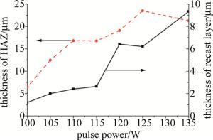
Figure 6. Thickness of recasting layer and HAZ varying with laser power
-
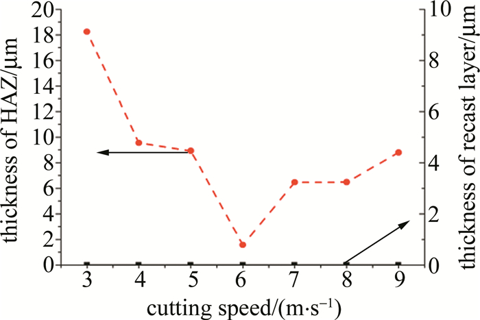
图 7为不同激光切割速率对支架重铸层及热影响区的影响规律。从图中看出, 热影响区厚度在切割速率小于6mm/s时, 随切割速率的增大而减小,大于6mm/s时, 随切割速率的增大而增大。用温度变化公式表示某点的热辐射强度:
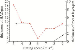
Figure 7. Thickness of recasting layer and HAZ varying with laser cutting speed
$ T(d) = \frac{{1000P}}{{4v{{({\rm{ \mathsf{ π} }}k)}^{\frac{1}{2}}}}}\exp \left( {\frac{{ - {d^2}}}{{4{k_1}}}} \right) $
(1) 式中, T为316L不锈钢某点温度;d为材料上某点到切缝中心的垂直距离;P为激光功率;v为激光切割速率;k为固定值,与316L不锈钢的比热及密度有关;k1也为固定值,与316L医用不锈钢的热扩散率有关。若切割速率v越低,根据(1)式可知,材料上同一点处温度越高,则代表光斑的热辐射越强,导致激光向熔体区传递的热量增多,而切割速率的变化与光斑的能量分布无关即熔体区的分布在切割速率变化时为恒定值,因此熔体区融化状态下所需的热量也为恒定值,则受热区吸收的热量越多,热影响区的厚度越大。当切割速率增大至6mm/s时,热影响区厚度本应减小,但是由于辅助气体喷头与光斑直径同轴且共同作用,当切割速率增大时,辅助气体与被融化的材料接触时间变短,导致吹走的热量减小,残留在材料内部的热量增多,导致热影响区厚度增加。当切割速率在3mm/s~9mm/s之间变化时,由于激光与管材充分作用,导致形成的熔体在反冲动量及激光的不断冲击下完全流出切缝侧面,故无明显的重铸层厚度产生。当切割速率在3mm/s~9mm/s之间变化时,热影响区分布范围为2.0μm~21.0μm,图 8为当切割速率为5mm/s时SEM检测支架热影响区的分布情况。
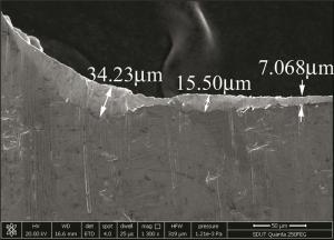
Figure 8. The distribution of stent HAZ with 5mm/s cutting speed
-
从峰值功率密度及激光占空比两个角度分析了激光工艺参量对重铸层及热影响区的影响规律。
(1) 支架重铸层厚度受脉冲宽度及脉冲功率影响,随脉宽及功率的增大而增大;当脉冲频率为20μs时,重铸层最小厚度为3.0μm;当脉冲频率为40μs时,支架重铸层最大厚度为37.4μm。
(2) 支架热影响区厚度受脉冲宽度、脉冲频率、激光功率及切割速率影响,随脉频及脉宽的增大而增大,当功率低于125W时,随功率的增大而增大,功率高于125W时,随功率的增大而减小;当切割速率低于6mm/s时, 随切割速率的增大而减小,切割速率高于6mm/s时,随切割速率的增大而增大;当脉冲频率为5000Hz时, 支架热影响区最小厚度为0.2μm;当激光功率为125W时, 支架热影响区最大厚度为23.5μm。
激光参量对血管支架重铸层及热影响区的影响
Effect of laser parameters on recasting layer and heat affected zone of cardiovascular stents
-
摘要: 为了探究光纤微秒激光加工中关键工艺参量对心血管支架重铸层和热影响区的形成机理及变化趋势, 采用了基于不同单因素参量下光纤微秒激光切割316L医用不锈钢的实验方法。通过进行理论分析和实验验证, 得到了单因素参量下316L心血管支架的实物模型及其热影响区及重铸层的检测数据。结果表明, 重铸层厚度主要受脉冲宽度及激光功率影响, 随脉冲宽度和脉冲功率的增大而增大, 当脉宽为20μs时, 最小重铸层厚度为3.0μm; 热影响区厚度与脉冲宽度、脉冲频率、激光功率、切割速率有关, 即随脉冲宽度及脉冲频率的增大而增大, 随功率的增大先增大后减小, 随切割速率的增大先减小后增大, 当脉冲频率为5000Hz时, 最小热影响区厚度为0.2μm。通过研究316L心血管支架重铸层及热影响区的形成机理及变化趋势, 为后续的正交实验及抛光实验奠定了基础。Abstract: In order to explore the formation mechanism and the changing trend of recast layer and heat affected zone (HAZ) of cardiovascular stents induced by key technological parameters in optical fiber microsecond laser processing, experimental method of cutting 316L medical stainless steel by optical fiber microsecond laser based on different single factor parameters was adopted. Through theoretical analysis and experimental verification, the physical model of 316L cardiovascular stent and the detection data of HAZ and recast layer were obtained under single factor parameters. The results show that the thickness of recast layer is mainly affected by pulse width and laser power. It increases with the increase of pulse width and power. The minimum thickness of recast layer is 3.0μm when the pulse width is 20μs. The thickness of HAZ is related to pulse width, pulse frequency, laser power and cutting rate. It increases with the increase of pulse width and frequency. With the increase of power, it increases first and then decreases. With the increase of cutting rate, it decreases first and then increases. When pulse frequency is 5000Hz, the minimum HAZ thickness is 0.2μm. The study of the formation mechanism and trend of recast layer and HAZ of 316L cardiovascular stents gives a foundation for subsequent orthogonal and polishing experiments.
-
Figure 1. Laser equipment and cardiovascular stent
a—TLS-HT1100 cardiovascular stent laser cutting machine b—the cardiovascular stent after fiber laser cutting and partial enlargement
Table 1. The range of laser process parameters
pulse power pulse width pulse frequency cutting speed 50W~150W 1μs~10ms 1Hz~10000Hz 0mm/s~10mm/s  下载: 导出CSV
-
[1] LIU L, LI D B, TONG Y F, et al. Laser processing technology and research progress of vascular stent [J]. Hot Working Technology, 2017, 46(5):15-18(in Chinese). [2] MENG H Y, LIAO J H, GUAN B G, et al.Fiber laser cutting technology on coronary artery stent[J]. Chinese Journal of Lasers, 2007, 34(5):733-736(in Chinese). [3] CHEN Zh, WANG J L, LI Y T, et al.Preparation of coronary stent with 316L stainless steel seamless thin-wall tube[J]. Heat Treatment of Metals, 2008, 33(2):76-78(in Chinese). [4] FAN W, GAO F, XIE J F.Study on laser fine cutting process of stainless coronary stent[J].Materials Reviews, 2012, 26(22):27-30(in Chinese). [5] ZHANG Y Zh, ZHANG Ch, LI J, et al.Formation mechanism of recast layer in millisecond laser drilling of Ti6AlV alloys[J].Acta Optica Sinica, 2017, 37(2):144-153(in Chinese). [6] FU C H, LIU J F, GUO A. Statistical characteristics of surface integrity by fiber laser cutting of Nitinol vascular stents[J]. Applied Surface Science, 2015, 353:291-299. doi: 10.1016/j.apsusc.2015.06.105 [7] MUHAMMAD N, WHITEHEAD D, BOOR A, et al. Picosecond laser micromachining of nitinol and platinum-iridium alloy for coronary stent applications[J]. Applied Physics, 2012, A106(3):607-617. [8] YANG H, HUANG Sh, DUAN J, et al.Contrastive study on laser ablation of single-crystal silicon by 1030nm femtosecond laser and 355nm nanosecond laser[J].Chinese Journal of Lasers, 2013, 40(1):0103003(in Chinese). doi: 10.3788/CJL [9] YAO Zh Q, HU Y X. Direct fabrication of sub-micron sized mirco-structure by interfering nanosecond laser beams[J].Journal of Mechanical Engineering, 2013, 49(6):122-128(in Chinese). doi: 10.3901/JME.2013.06.122 [10] ZHOU X, DUAN J, CHEN H, et al.Experimental study about water-assisted laser drill on Al2O3 ceramics without recast layer[J].Laser Technology, 2018, 42(2):271-275(in Chinese). [11] ZHOU Y H, LIAO J H, MENG H Y, et al.Laser micro-fabrication of endovascular stent[J].Applied Laser, 2005, 25(3):161-164(in Chinese). [12] HUANG Ch B, AO N J.Novel biodegradable coronary stents: design and laser microprocessing[J].Applied Laser, 2007, 27(3):224-227(in Chinese). [13] WANG, K D, DUAN W Q, MEI X S, et al.Processing of micro-hole by millisecond laser and post processing of recast layer[J].Journal of Xi'an Jiaotong University, 2011, 45(7):45-49(in Chinese). [14] HOCK K, ADELMANN B, HELLMANN R. Comparative study of remote fiber laser and water-jet guided laser cutting of thin metal sheets[J]. Physics Procedia, 2012, 39:225-231. doi: 10.1016/j.phpro.2012.10.033 [15] JIANG M H, ZHAI L B, CHEN J M.Experimental study on laser micro cutting cobalt chromium tube[J].Journal of Microfabrication Technology, 2008(4):27-31(in Chinese). [16] CHENG P, WEI D, WU B K, et al.Laser micro-fabrication of endovascular stent[J].Optics and Precision Engineering, 2014, 22(1):63-68(in Chinese). doi: 10.3788/OPE. [17] MUHAMMAD N, LI L.Underwater femtosecond laser micromachining of thin nitinol tubes for medical coronary stent manufacture[J].Applied Physics, 2012, A107(4):849-861. [18] LI C, JOHNSON D, KOVACEVIC R. Modeling of waterjet guided laser grooving of silicon[J]. International Journal of Machine Tools & Manufacture, 2003, 43(9):925-936. [19] ZHANG X B. Laser drilling with 100ns~700ns YAG laser in Nickel-based alloy[J]. Applied Laser, 2005, 25(2):90-92(in Chinese). [20] LI C, NIKUMB S, WONG F. An optimal process of femtosecond laser cutting of NiTi shape memory alloy for fabrication of miniature devices[J]. Optics and Lasers in Engineering, 2005, 44(10):1078-1087. [21] MANLEY J, HOUSH R, WAGNER F, et al. Water-guided lasers create clean cuts[J]. Laser Focus World, 2004, 40(5):15-18. -

 点击查看大图

图(8) / 表(1)
计量
- 文章访问数: 5555
- HTML全文浏览量: 3681
- PDF下载量: 21
- 被引次数: 0
