 网站地图
网站地图

 下载:
下载:


-
与传统的强度调制直接探测技术相比,相干光通信具有更高的接收机灵敏度,可以支持更多的高阶调制格式,且能够在电域中提取光场的全部信息。正交相移键控(quadrature phase-shift-keying,QPSK)相对传统的开关键控可以提高频谱效率且对信号传输损耗具有恢复能力[1-3]。由于同相正交(in-phase quadrature, IQ)调制器的非理想偏置、混频器共轭不对称、光电探测器响应度失配等[4]引起的接收端正交失衡,影响QPSK信号的解调,造成系统性能降低,这就需要专门的补偿算法来消除其影响[5-6]。
2008年, FATADIN等人[7]对QPSK相干接收机中的正交失衡(quadrature imbalance,QI)补偿算法进行了理论仿真分析,采用施密特正交化(Gram-Schmidt orthogonalization procedure,GSOP)补偿正交失衡。2009年, SUN等人[8]进一步研究了QI会造成相干接收机性能下降,采用椭圆拟合算法补偿以后,系统光信噪比损耗从6dB到1dB,性能得到提升。PETROU等人[9]提出了一种基于恒模算法(constant modulus algorithm,CMA)的新型盲自适应QI补偿方案进行补偿。2013年, FARUK等人[10]提出一种新型的有限脉冲响应滤波器配置方案实现QI补偿,可以补偿所有的QI问题。2014年, NGUYEN等人[11]提出一种最大信噪比(signal-to-noise ratio,SNR)估计法对QI补偿,这种算法更适合实时信号处理。2016年WANG等人[6]在相干光正交频分复用系统中采用了最小均方误差(minimum mean square error,MMSE)方法实现QI补偿,仿真表明, MMSE补偿算法在光信噪比损耗方面优于传统算法。2017年, FARUK等人[12]在高阶调制格式下分析了GSOP和对称正交化两种QI补偿算法。由于GSOP算法实现复杂度较低,更适合解决本文中的QI补偿问题。
近几年业内人士对适用于高阶调制格式的载波恢复算法也展开了大量的工作,以降低实现复杂度改善系统性能。2012年, MAGARINI等人[13]在偏振复用正交相移键控相干接收系统中采用前馈导频符号辅助载波相位恢复方案,该方案的主要优点是避免了周期滑动之后的相位模糊问题。2014年, FLUDGER等人[14]仿真分析了两种新型的低复杂度多级数字前馈载波相位估计算法,这两种算法对于激光相位噪声具有较高的容限。2015年, PAJOVIC等人[15]提出了一种新型的导频符号辅助的低复杂度载波相位估计算法。2017年, FARUK等人[12]在相干收发机中高阶调制格式下采用盲估计和导频辅助估计两种算法实现载波恢复。由于传统的锁相环法(phase-locked loop,PLL)适用于各种调制格式,且复杂度较低,因此这里采用锁相环法实现载波恢复。
本文中对相干光通信系统中QPSK调制解调做实验研究,通过复杂度较低的GSOP算法实现QI补偿,设计松尾环来实现载频的跟踪、捕获,完成载波恢复功能,最后实现符号的抽样判决和正确解调。
-
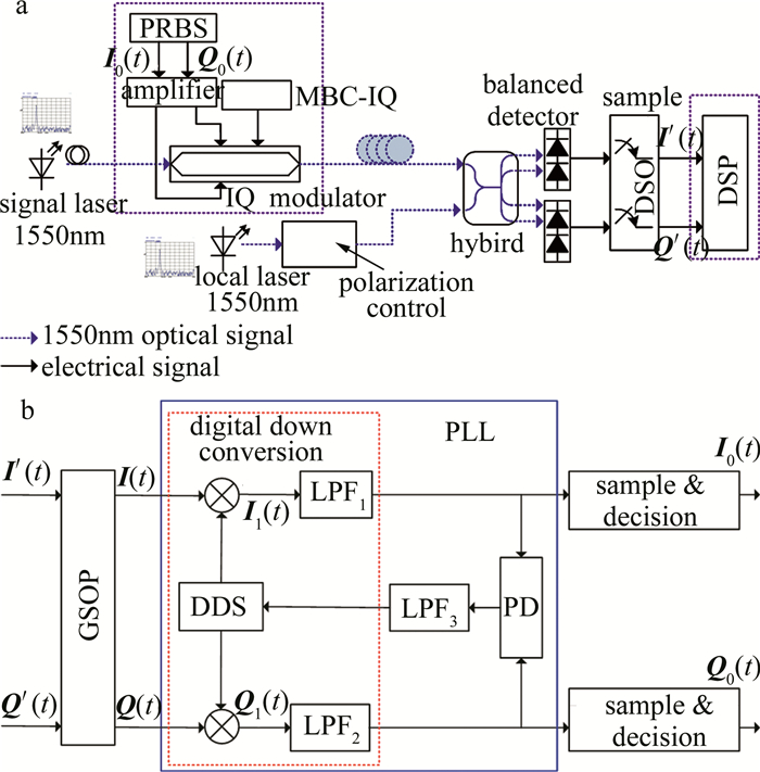
图 1是相干光通信系统原理框图。其工作原理如下:由于评估板的工作电压是100mV~500mV,两路伪随机二进制序列(pseudo-random binary sequence,PRBS)信源的输出电压取300mV,随后将波特率为8MHz的两路信源输入电压放大器放大电压至满足调制器正常工作后,将两路信号输入到IQ调制器完成QPSK调制,得到已调信号。接收端接收到信号光(1550nm),和已调节好偏振态的本振光信号(1550nm)输入混频器实现相干混频,再经过平衡探测器输出至示波器进行采样,并在PC机实现离线解调。本文中主要是对图 1a中接收机输出的I、Q信号用示波器采集并进行离线数据分析,如图 1a中虚线部分,其中,图 1a中MBC-IQ(in-phase quadrature modulator bias controller)是同相正交偏压控制器。图 1b是图 1a中的数字信号处理(digital signal processing,DSP)实现原理图。在DSP中,实线框是锁相环实现原理,虚线框是数字下变频,LPF1是低通滤波器(low pass filter, LPF),LPF2是环路滤波器,PD(phase detector)是鉴相器。
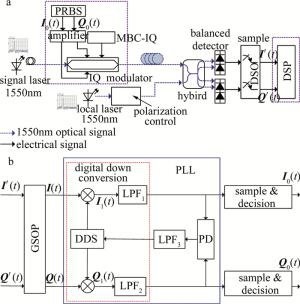
Figure 1. a—schematic diagram of a coherent optical communication system b—block diagram of intermediate frequency (IF) signal analysis
-
经过相干接收机输出理想的I路和Q路两路信号是完全正交的。但在实际系统中, 由于:(1)I, Q两路偏置点、相位控制的偏置点与理论值存在偏差;(2)90°光混频器因共轭不对称造成相位偏置不是90°;(3)光电二极管的响应度不匹配等原因,造成I路和Q路的幅度不能保持一致,相位不完全正交[16]。幅度不一致造成信噪比降低,不影响信号的解调,而相位不正交就会造成不能正确的解调信号及星座图旋转[17],造成系统误比特率增加,系统性能下降。
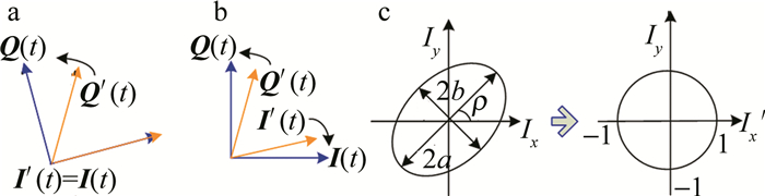
常用以下几种补偿算法来消除其影响:施密特正交化[7]、对称正交化(简称Löwdin正交化)[12]、椭圆拟合算法[8]、恒模算法[9]。这3种算法的原理图如图 2所示。
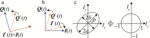
Figure 2. a—Gram-Schmidt orthogonalization b—symmetric orthogonalization c—ellipse fitting algorithm
由图 2可知,GSOP算法由于计算复杂度较低而广泛地应用于解决QI补偿。其实现原理如下式所示:
$ \left[\begin{array}{l}{\boldsymbol{I}(t)} \\ {\boldsymbol{Q}(t)}\end{array}\right]=\left[\begin{array}{cc}{1} & {0} \\ {-m} & {n}\end{array}\right]\left[\begin{array}{l}{\boldsymbol{I}^{\prime}(t)} \\ {\boldsymbol{Q}^{\prime}(t)}\end{array}\right] $
(1) 即I(t)=I′(t),Q(t)=nQ′(t)-mI′(t)。其中,m,n为校正系数,I′(t)和Q′(t)分别是已调输出的相位不完全正交的I路和Q路信号,I(t)和Q(t)是经过QI补偿的I路和Q路信号。
若相干接收机输出的两路电信号为:
$ \boldsymbol{I}^{\prime}(t)=\alpha A_{\mathrm{s}} A_{1} \cos \left(\omega_{\mathrm{IF}} t+\theta\right) $
(2) $ \boldsymbol{Q}^{\prime}(t)=\alpha A_{\mathrm{s}} A_{1} \sin \left(\omega_{\mathrm{IF}} t+\theta+\psi\right) $
(3) 式中,α为光电探测器的灵敏度;ωIF, As, Al分别是中频信号的频率、信号光和本振光的幅度;θ和θ+ψ分别是相干接收机输出的两路中频信号的相位。
当m, n的值分别为m=tanψ, n=1/cosψ时,可得中频信号经过GSOP补偿后的两路信号为:
$ \boldsymbol{I}(t)=\alpha A_{\mathrm{s}} A_{1} \cos \left(\omega_{\mathrm{IF}} t+\theta\right) $
(4) $ \boldsymbol{Q}(t)=\alpha A_{{\rm s}} A_{1} \sin \left(\omega_{\mathrm{IF}} t+\theta\right) $
(5) -
本文中采用松尾环实现载频的跟踪、捕获。松尾环的鉴相特性是矩形特性,通过矩形振荡状态来分析锁相环的锁定状态。锁相环由数字下变频、数字鉴相器(PD)、环路滤波器三部分组成,下面对这部分实现原理进行分析[18]。
假定由直接数字频率合成器(direct digital synthesizer,DDS)产生的本地载波信号为:
$ \mathit{\boldsymbol{S}} = 2\frac{1}{{\alpha {A_{\rm{s}}}{A_1}}}\cos \left( {{\omega _{{\rm{IF}}}}t + \phi } \right) $
(6) 式中, ϕ是本地载波信号的初始相位,经过乘法器相乘后得到的两路信号为:
$ \begin{array}{*{20}{c}} {{\mathit{\boldsymbol{I}}_1}(t) = \mathit{\boldsymbol{I}}(t) \cdot \mathit{\boldsymbol{S}} = }\\ {\cos \left( {2{\omega _{IF}}t + \theta + \phi } \right) + \cos (\theta - \phi )} \end{array} $
(7) $ \begin{array}{*{20}{c}} {{\mathit{\boldsymbol{Q}}_1}(t) = \mathit{\boldsymbol{Q}}(t) \cdot \mathit{\boldsymbol{S}} = }\\ {\sin \left( {2{\omega _{{\rm{IF}}}}t + \theta + \phi } \right) + \sin (\theta - \phi )} \end{array} $
(8) 再通过低通滤波器滤除二倍频后,得到的两路基带信号为:
$ \mathit{\boldsymbol{I}}_0^\prime (t) = \cos (\theta - \phi ) $
(9) $ \boldsymbol{Q}_{0}^{\prime}(t)=\sin (\theta-\phi) $
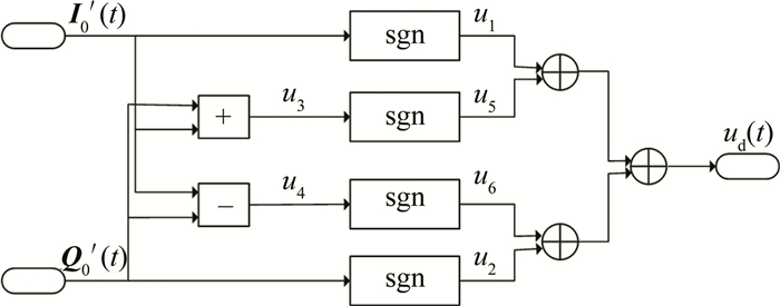
(10) 输出的两路信号通过鉴相器得到相位误差信号ud(t),其反映的是环路跟踪相位的程度,鉴相器的设计原理如图 3所示。
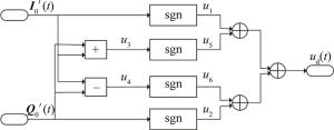
Figure 3. Phase detector schematic
由鉴相器的原理可知,基带信号I0′(t), Q0′(t)经鉴相输出相位误差信号为[19]:
$ \begin{aligned} u_{\mathrm{d}}(t)=u_{1} & \oplus u_{2} \oplus u_{5} \oplus u_{6}=\operatorname{sgn}\left(u_{1} u_{2} u_{5} u_{6}\right)=\\ & \operatorname{sgn}\left[\boldsymbol{I}_{0}^{\prime}(t) \boldsymbol{Q}_{0}^{\prime}(t) u_{3} u_{4}\right] \end{aligned} $
(11) 式中,u1=sgn[I0′(t)],u2=sgn[Q0′(t)],u3=I0′(t)+Q0′(t),u4=I0′(t)-Q0′(t),u5=sgn(u3),u6=sgn(u4)。⊕的运算规则如下式所示:
$ \begin{array}{c} {\mathop{\rm sgn}} A \oplus {\mathop{\rm sgn}} B = {\mathop{\rm sgn}} (AB) = \\ \left\{ {\begin{array}{*{20}{l}} { + 1, (A, B符号相同)}\\ { - 1, (A, B符号不同)} \end{array}} \right. \end{array} $
(12) 式中, A和B是两个变量。则将(9)式、(10)式、(12)式带入(11)式可得鉴相器输出的误差信号ud(t)为下式所示:
$ \begin{array}{l}{u_{\mathrm{d}}(t)=\boldsymbol{I}_{0}^{\prime}(t) \boldsymbol{Q}_{0}^{\prime}(t)\left[\boldsymbol{I}_{0}^{\prime}(t)+\boldsymbol{Q}_{0}^{\prime}(t)\right] \times} \\ {\left[\boldsymbol{I}_{0}^{\prime}(t)-\boldsymbol{Q}_{0}^{\prime}(t)\right]=\frac{1}{4} \operatorname{sgn}\{\sin [4(\theta-\phi)]\}}\end{array} $
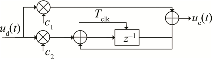
(13) 误差信号ud(t)再通过环路滤波器,一方面抑制输入噪声,另一方面还能通过环路参量调节环路的校正速度[20]。这里使用常用的二阶理想环路滤波器,其结构图如图 4所示。

Figure 4. Loop filter schematic
其对应的数字化系统函数为:
$ F(z)=c_{1}+\frac{c_{2} z^{-1}}{1-z^{-1}} $
(14) 环路系数c1和c2分别为:$c_{1}=\frac{2 \xi \omega}{K}, c_{2}=\frac{\omega^{2} T}{K} $。其中,ξ为阻尼系数,取值为0.707;K=2πfs(fs=10G sample/s)为环路增益,T为采样周期,Tclk为环路更新周期,ω为环路自然角频率;对于理想二阶环路滤波器,环路等效噪声带宽为:$B_{1}=\frac{\omega}{8 \xi}\left(1+4 \xi^{2}\right) $。其中,Bl取小于10倍的数据速率:Bl=0.1R,R是波特率,代入可得Bl=0.53ω,则可得:c1=3.397×10⁻⁵,c2=3.626×10⁻⁹。
-
在相干解调中,要正确地解调出初始码元,位同步是不可或缺的。要正确地恢复出基带信号,就需要知道接收码元的起止时刻,进行正确地抽样判决,以恢复出正确的基带信号,这里采用直接抽样判决的方法来实现位同步。在经过滤波的基带信号中确定码元的起始位置,在每个码元的中间时刻进行抽样并对其进行判决。根据调制编码原理分析,恢复信号的判决规则如下:若I0′(t)>0,判决结果为I0(t)=1;若I0′(t) < 0,判决结果为I0(t)=0;Q路判决规则同I路。
通过松尾环正确的追踪、捕获,再经过正确的抽样判决,I, Q两路信号得到正确解调。
-
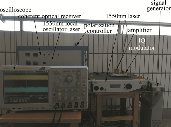
图 5是相干光通信系统实验架构图。
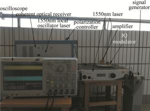
Figure 5. Experimental diagram of coherent optical communication
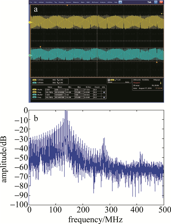
图 6a、图 6b分别是经平衡探测器输出的两路QPSK中频信号时域波形图(如图 1a中的I′(t)和Q′(t)所示)及处理所得的Q路信号频谱图。

Figure 6. a—IF signal waveform diagram of I-channel and Q-channel channel for QPSK b—spectrum diagram of Q-channel channel signal
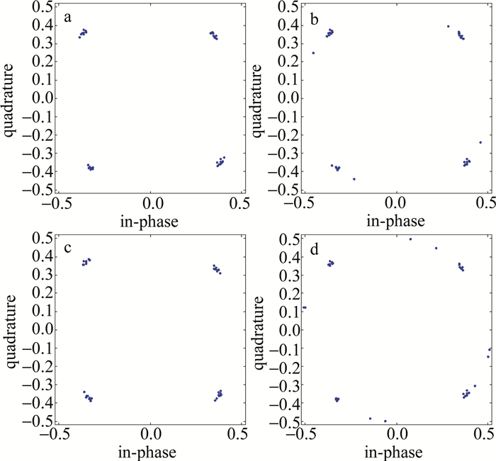
图 7a、图 7b分别是输出中频信号未加QI补偿算法和加QI补偿算法的星座图。由图 7a可知,未经过QI补偿的星座图呈椭圆趋势分布;经过QI补偿后,星座图的旋转得到修正。图 7c、图 7d分别是经解调后基带信号未加QI补偿算法和加QI补偿算法的对应的星座图。由图 7c知,未经QI补偿的星座点不完全集中且相对原点的距离不相等,经QI算法补偿后,星座点聚集性更好,且原点到星座点之间的距离也得到修正。
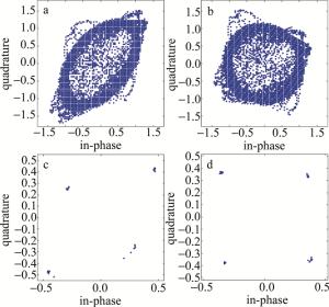
Figure 7. Constellation diagram
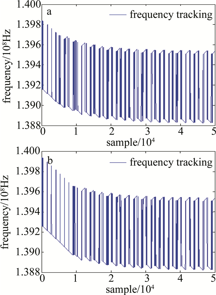
图 8a、图 8b分别是频偏为300kHz, 400kHz对应的频率跟踪图。由图对比可知,频偏为300kHz相对频偏为400kHz锁相环更快完成载频的跟踪捕获,相位锁定所需的采样点更少。
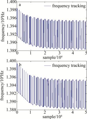
Figure 8. Frequency tracking diagram corresponding to different frequency offsets
图 9a~图 9d分别是频偏为300kHz, 400kHz, -300kHz, 500kHz对应的星座图。由图对比可知,在频偏为±300kHz时,调制点聚集性能较好,信号得到正确解调;在频偏为400kHz和500kHz时,调制点分布较散,聚集性能差,信号不能完全正确解调,在频偏为-400kHz信号亦不能完全正确解调。则可知,在频偏为-300kHz~300kHz范围内,锁相环能准确地对载频实现跟踪、捕获,完成基带信号完全解调。

Figure 9. Constellation diagram corresponding to different frequency offsets
图 10a~图 10c分别是未经过QI补偿算法的Q路基带信号、经过QI补偿算法得到的Q路基带信号、经过QI补偿得到的I路基带信号。可知未经过QI补偿的基带信号波形发生畸变,影响到信号解调结果的正确性,进而影响系统的误码性能,而经过QI补偿的信号波形畸变得到了修正,且信号得到正确解调。
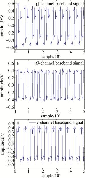
Figure 10. Baseband signal
-
(1) 相干光通信系统中由于IQ调制器的偏置点与理论值存在偏差、接收端90°光混频器相位的非理想偏置以及平衡探测器的缺陷等其它原因的影响,会造成星座图旋转,解调误码。采用GSOP进行QI补偿后,星座图旋转得到修正,基带信号的畸变得到修正。
(2) 信号在相干解调时,频率漂移影响信号无法正确解调。通过松尾环实现载频的跟踪、捕获,得到正确的解调信号。当频偏为-300kHz~300kHz时,锁相环可以锁定,解调出正确的信号。该方案实现复杂度低,易于实现,在相干光通信系统中具有一定的研究意义。
相干光通信系统中QPSK调制解调实验研究
Experimental study about QPSK modulation and demodulation in coherent optical communication systems
-
摘要: 为了使相干接收机输出的两路信号相位正交, 正确地解调信号, 采用施密特正交化算法对两路信号进行了理论分析和实验验证, 经正交失衡算法补偿后, 星座图的性能得到改善; 通过松尾环实现载频的跟踪、捕获以达到载波恢复, 实现了基带信号正确解调。结果表明, 经施密特正交化算法补偿后, 旋转的星座图得到了修正, 星座点间的欧几里德距离不相等问题得到修正, 基带信号畸变得到了改善; 当频偏在-300kHz~300kHz范围内, 松尾环可以实现载频的跟踪、捕获, 基带信号实现正确解调。该方案实现复杂度低, 切实可行, 适用于相干光通信系统的研究。Abstract: In order to make the received two signals orthogonal to each other and correctly demodulate the signal, Schmitt orthogonalization algorithm was used to theoretically analyze and experimentally verify the two signals. The performance of constellation was improved after orthogonal imbalance compensation. The carrier frequency was tracked and captured by the loose tail ring to achieve carrier recovery, and the baseband signal was demodulated correctly. The experimental results show that, after compensation by Schmidt orthogonalization algorithm, the rotated constellation is corrected and the problem of unequal Euclidean distance between constellation points is improved. The baseband signal distortion becomes corrected. When the frequency offset is in the range of -300kHz~300kHz, the loose tail loop can track and capture carrier frequency and baseband signal can be correctly demodulated. The scheme is low complexity and practical, and is suitable for the study of coherent optical communication systems.
-
Figure 1. a—schematic diagram of a coherent optical communication system b—block diagram of intermediate frequency (IF) signal analysis
Figure 2. a—Gram-Schmidt orthogonalization b—symmetric orthogonalization c—ellipse fitting algorithm
Figure 6. a—IF signal waveform diagram of I-channel and Q-channel channel for QPSK b—spectrum diagram of Q-channel channel signal
Figure 7. Constellation diagram
a—without QI compensation b—with QI compensation c—without QI compensation (only modulation points) d—with QI compensation (only modulation points)
Figure 8. Frequency tracking diagram corresponding to different frequency offsets
a—300kHz b—400kHz
Figure 9. Constellation diagram corresponding to different frequency offsets
a—300kHz b—400kHz c—-300kHz d—500kHz
-
[1] YOSHIDA T, SUGIHARA T, SAWADA K, et al. Polar coordinate transformation based dual binary-drive QPSK modulation[C]//Optical Fiber Communication. New York, USA: IEEE, 2010: OMK4. [2] YAN S, WENG X, GAO Y, et al. Generation of square or hexagonal 16-QAM signals using a dual-drive IQ modulator driven by binary signals[J]. Optics Express, 2012, 20(27):29023-29034. doi: 10.1364/OE.20.029023 [3] SUN H, WU K T, ROBERTS K. Real-time measurements of a 40Gb/s coherent system[J]. Optics Express, 2008, 16(2):873-879. doi: 10.1364/OE.16.000873 [4] CHUNG H S, SUN H C, KIM K, et al. Effects of carrier phase estimation on front-end IQ mismatch compensation in DP-QPSK coherent receiver[C]//Optoelectronics and Communications Conference Held Jointly with 2013 International Conference on Photonics in Switching. New York, USA: IEEE, 2013: TuPR_2. [5] SAVORY S J. Digital coherent optical receivers: algorithms and subsystems[J]. IEEE Journal of Selected Topics in Quantum Electronics, 2010, 16(5):1164-1179. doi: 10.1109/JSTQE.2010.2044751 [6] WANG X J, LEIBLE B, WANG W H, et al. Joint IQ imbalance compensation and channel estimation in coherent optical OFDM systems[C]//2016 10th International Conference on Signal Processing and Communication Systems. New York, USA: IEEE, 2016: 16653749. [7] FATADIN I, SAVORY S J, IVES D. Compensation of quadrature imbalance in an optical QPSK coherent receiver[J]. IEEE Photonics Technology Letters, 2008, 20(20):1733-1735. doi: 10.1109/LPT.2008.2004630 [8] SUN H C, CHUNG H S, KIM K. Impact of quadrature imbalance in optical coherent QPSK receiver[J]. IEEE Photonics Technology Lett-ers, 2009, 21(11):709-711. doi: 10.1109/LPT.2009.2016759 [9] PETROU C S, VGENIS A, ROUDAS I, et al. Quadrature imbalance compensation for PDM QPSK coherent optical systems[J]. IEEE Photonics Technology Letters, 2009, 21(24):1876-1878. doi: 10.1109/LPT.2009.2034750 [10] FARUK M S, KIKUCHI K. Compensation for in-phase/quadrature imbalance in coherent-receiver front end for optical quadrature am-plitude modulation[J]. IEEE Photonics Journal, 2013, 5(2):7800110. doi: 10.1109/JPHOT.2013.2251872 [11] NGUYEN T H, GOMEZ-AGIS F, GAY M, et al. IQ imbalance compensation based on maximum SNR estimation in coherent QPSK systems[C]//2014 16th International Conference on Transparent Optical Networks. New York, USA: IEEE, 2014: 14526430. [12] FARUK M S, SAVORY S J. Digital signal processing for coherent transceivers employing multilevel formats[J]. Journal of Lightwave Technology, 2017, 35(5):2-13. doi: 10.1109/JLT.2017.2683160 [13] MAGARINI M, BARLETTA L, SPALVIERI A, et al. Pilot-symbols-aided carrier-phase recovery for 100G PM-QPSK digital cohe-rent receivers[J]. IEEE Photonics Technology Letters, 2012, 24(9):739-741. doi: 10.1109/LPT.2012.2187439 [14] FLUDGER C R S, BOSCO G, BILAL S M, et al. Multistage carrier phase estimation algorithms for phase noise mitigation in 64-quadrature amplitude modulation optical systems[J]. Journal of Lightwave Technology, 2014, 32(17):2973-2980. doi: 10.1109/JLT.2014.2325064 [15] PAJOVIC M, MILLAR D, KOIKEAKINO T, et al. Multi-pilot aided carrier phase estimation for single carrier coherent systems[C]//Signal Processing in Photonic Communications. Washington DC, USA: The Optical Society of America, 2015: 3-4. [16] HOSSAIN M J, FARUK M S. An efficient scheme for receiver-side quadrature imbalance compensation in coherent optical receivers[C]// 2012 International Conference on Fiber Optics and Photonics. New York, USA: IEEE, 2012: 13597286. [17] FANG Y, GU Q. Angle statistical blind compensation method for IQ imbalance of QPSK signal [J]. System Simulation Technology, 2012, 8(2):87-92(in Chinese). [18] CHANG Q, BI C K, ZHANG Q Sh. The principle and implementation of Costas ring in DSSSK system[J]. Microcomputer Information, 2006, 22(35):241-242(in Chinese). [19] ZHANG X. Digital baseband signal processing algorithm for spread spectrum communication and its VLSI implementation [M]. Beijing: Science Press, 2004:113-115(in Chinese). [20] DU Y. MATLAB and FPGA implementation of digital communication synchronization technology[M]. Beijing: Publishing House of Electronics Industry, 2015:96-218(in Chinese). -

 点击查看大图
计量
- 文章访问数: 9716
- HTML全文浏览量: 7666
- PDF下载量: 31
- 被引次数: 0
