 网站地图
网站地图


-
光发射次模块(transmitter optical subassembly, TOSA)器件的耦合结构, 大都采用分立式透镜,其透镜球差和焦距限制了耦合效率。随着光纤微透镜加工技术的发展,光纤端面微透镜与激光直接耦合成为可能,耦合效率将大幅提升。
工程界主要采用的光纤微透镜有圆柱形、楔型、四角锥形、椭圆锥形等4种结构[1-5]。2007年,LU等人[6]首次提出非轴对称的光纤微透镜,耦合效率高达85%。2008年, HAN[7]提出利用带柱状楔型微透镜的多模光纤结构进行耦合,耦合效率最高可达87.05%。但这类微透镜加工较复杂且费时,偏心量难以控制。2011年,WU等人[8]利用SU-8光刻胶在多模光纤端面直接制作了非球面微透镜结构,耦合效率高达78%。随着近几年光纤微透镜端面加工技术的成熟,CHEN等人[9]研制了电弧熔炼工艺,制备出非对称的椭圆形微透镜端面,最大耦合效率达83%。2017年, LIN等人[10]通过机械研磨、玻璃层涂覆、静电延展三步制作出双曲面微透镜结构,耦合效率可以达到80%。近年来,有学者提出光纤微透镜端面研磨成楔形和双曲型[11-13]直接耦合进行光束会聚,其结构简单,耦合效率高达80%以上[14-15]。
本文中提出在光通信中采用大功率激光器与光纤直接耦合,利用分布式反馈激光器(distributed feedback laser,DFB)高纵横比激光光束,通过光纤微透镜直接耦合方法设计一种应用于高速通信的楔形截顶光纤微透镜耦合结构,耦合效率可达84.40%。
-
DFB激光器快轴发散角通常大于慢轴发散角[16], 其远场分布通常呈椭圆锥形。远场光束分布结构如图 1所示。
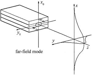
Figure 1. Far-field distribution structure of DFB laser
假设光束不受有源层狭缝作用,光束模型为基模高斯光束。光束束腰位于半导体激光器出光面z0, 其处光场分布为:
$ E(x, y)=\exp \left(-\frac{x^{2}}{w_{0 x}^{2}}-\frac{y^{2}}{w_{0 y}^{2}}\right) $
(1) 式中,x和y分别为z0处快轴和慢轴坐标,w0x和w0y分别为光束快轴和慢轴方向上的束腰半径。
DFB激光器的远场分布可由基模高斯光束经菲涅耳衍射定理得到, 经端面狭缝衍射可得光束在z1处的波函数, 表达式为:
$ \begin{array}{l} E\left( {x, y, {z_1}} \right) = \frac{{ - {\rm{i}}k\exp \left( {{\rm{i}}k{z_1}} \right){w_{0x}}{w_{0y}}}}{{\sqrt {\left( {2{z_1} - {\rm{i}}kw_{0x}^2} \right)\left( {2{z_1} - {\rm{i}}kw_{0y}^2} \right)} }} \times \\ \exp \left[ {\frac{{{\rm{i}}2k{z_1}{x^2}}}{{4z_1^2 + {{\left( {kw_{0x}^2} \right)}^2}}} + \frac{{{\rm{i}}2k{z_1}{y^2}}}{{4z_1^2 + {{\left( {kw_{0y}^2} \right)}^2}}}} \right] \times \\ \exp \left[ { - \frac{{{{\left( {k{w_{0x}}x} \right)}^2}}}{{4z_1^2 + kw_{0x}^2}} - \frac{{{{\left( {k{\omega _{0y}}y} \right)}^2}}}{{4z_1^2 + kw_{0y}^2}}} \right] \end{array} $
(2) 式中, k为波数。根据高斯光束束腰半径和曲率半径的表达形式:
$ \left\{ {\begin{array}{*{20}{l}} {{w_x}\left( {{z_1}} \right) = {w_{0x}}\sqrt {1 + {{\left( {\frac{{\lambda {z_1}}}{{{\rm{ \mathtt{ π} }}w_{0x}^2}}} \right)}^2}} }\\ {{w_y}\left( {{z_1}} \right) = {w_{0y}}\sqrt {1 + {{\left( {\frac{{\lambda {z_1}}}{{{\rm{ \mathtt{ π} }}w_{0y}^2}}} \right)}^2}} }\\ {{R_x}\left( {{z_1}} \right) = {z_0}\left[ {1 + {{\left( {\frac{{{\rm{ \mathtt{ π} }}w_{0x}^2}}{{\lambda {z_1}}}} \right)}^2}} \right]}\\ {{R_y}\left( {{z_1}} \right) = {z_1}\left[ {1 + {{\left( {\frac{{{\rm{ \mathtt{ π} }}w_{0y}^2}}{{\lambda {z_1}}}} \right)}^2}} \right]} \end{array}} \right. $
(3) 式中, wx(z1), wy(z1)分别为z1处x, y方向上的束腰半径;Rx(z1), Ry(z1)分别为z1处波阵面在x, y方向上的曲率半径, λ为波长。将(3)式代入(2)式, 可得DFB激光器远场分布特性方程:
$ \begin{array}{l} E\left( {x, y, {z_1}} \right) = \frac{{ - {\rm{i}}k\exp \left( {{\rm{i}}k{z_1}} \right){w_{0x}}{w_{0y}}}}{{\sqrt {\left( {2{z_1} - {\rm{i}}kw_{0x}^2} \right)\left( {2{z_1} - {\rm{i}}kw_{0y}^2} \right)} }} \times \\ \exp \left\{ {\frac{{\mathit{k}{\mathit{x}^2}}}{{{{\left[ {{w_x}\left( {{z_1}} \right)} \right]}^2}}} + \frac{{k{y^2}}}{{{{\left[ {{w_y}\left( {{z_1}} \right)} \right]}^2}}}} \right\} \times \\ \exp \left[ { - \frac{{{\rm{i}}{k^2}}}{{2{R_x}\left( {{z_1}} \right)}} - \frac{{{\rm{i}}{y^2}}}{{2{R_y}\left( {{z_1}} \right)}}} \right] \end{array} $
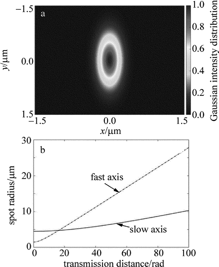
(4) 基于(4)式DFB激光器远场分布特性,参考DFB激光器的电光特性参量对激光器光束传播进行数值仿真可得,快慢轴光斑半径与传播距离关系如图 2所示。从图 2b看出, 随着传播距离的增大,快轴和慢轴的光斑半径增大且在传播20μm后快轴方向发散角大于慢轴,相差20°左右。故在设计耦合结构需要对快慢轴不同发散角采取不同的处理方式。

Figure 2. Light field distribution characteristics of DFB laser
-
为使尽可能多的光束到达光纤端面时耦合入纤,光斑半径和快慢轴发散角都应满足发散角的正弦值小于光纤数值孔径[17]。DFB激光的发散为非轴对称,常用DFB激光器慢轴和快轴发散角全角分别为15°~25°和35°~45°。设计结构为满足DFB激光器不同发散角光束的整合,本文中使用多模光纤G.651,DFB激光器快轴发散角θf和慢轴发散角θs分别取25°和45°,光纤数值孔径为dNA=0.277。
由sin(12.5°)=0.216<dNA,sin(22.5°)=0.383>dNA看出快轴方向不满足耦合条件。故设计快轴方向光束的耦合结构使其满足耦合条件。快轴耦合结构参量设计包括耦合距离、斜面倾角、端面宽度。
楔形光纤微透镜耦合距离和半斜面倾角设计示意图如图 3所示。
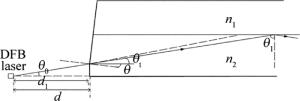
Figure 3. Schematic diagram of coupling distance and bevel angle
选取快轴发散角临界值θmax, 可求其耦合距离。
$ \tan \left( {22.5°} \right) \times d = 25 $
(5) 计算耦合距离d=60μm。为减少不同入射角引起的色散,根据斯涅尔折射定律可得θ:
$ \begin{array}{*{20}{c}} {\sin \left( {\theta + {\theta _0}} \right) = {n_1}\sin \left( {{\theta _{\rm{t}}} + \theta } \right) = }\\ {{n_1}\sin \left[ {\arccos \left( {\frac{{{n_2}}}{{{n_1}}}} \right) + \theta } \right]} \end{array} $
(6) 式中, θ0为光束入射角,θt为光纤光束与水平线夹角。当θ0取θmin=arcsin(dNA)=0.28rad时,代表快轴方向恰好能耦合入纤的光束临界发散角。当θ0取θmax=22.5°(即0.39rad)时,对应的是光束的最大发散角的光束,经楔形透镜后应该满足光纤的传播条件。当θ0取值介于两者之间时,理论上DFB光束进入纤芯后可以束缚在纤芯中进行传播。通过MATLAB解得θ= 0.2rad或θ=0.6rad。得到高耦合效率的同时,为使光束尽量平行轴心传输,因此斜面倾角θ=0.6rad。
耦合距离和斜面倾角确定后,由下式可计算端面的半宽度D/2=30μm。
$ \left\{\begin{array}{l}{\frac{D}{2}+\frac{\left(d-d_{1}\right)}{\tan \left(\theta_{\max }\right)}=25} \\ {D=2 \tan \left(\theta_{\max }\right) d_{1}}\end{array}\right. $
(7) -
本文中采用ZEMAX非序列光纤追迹方法搭建仿真实验。DFB激光器快轴与慢轴的最大发散全角分别为45°和25°,波长为1310 nm;光纤采用G.651多模光纤,其纤芯折射率为1.491,直径为50μm, 包层折射率为1.465、外直径为142μm。搭建DFB激光与光纤直接耦合,球透镜下DFB激光与光纤的分立式耦合结构,楔形截顶微透镜耦合3种耦合结构。其中楔形截顶微透镜耦合结构和直接耦合结构中出光端面到光纤端面的距离为60μm;分立式耦合在聚焦透镜半径为7.5mm, 折射率为1.523,出光端面到球心距离为1.5mm,球心到光纤端面的距离为3.3mm。结构如图 4所示。
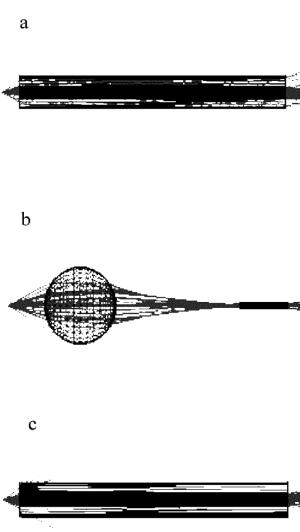
Figure 4. a—direct coupling b—discrete ball-lens coupling c—microlens coupling
-
在ZEMAX中建立仿真模型对比耦合效率、耦合距离、容忍度。结果如表 1所示。
Table 1. Comparison of coupling distance and coupling efficiency of three structures
structure direct coupling discrete coupling wedge shaped microlens distance 60μm 4.8mm 60μm optical power/W 1.037 1 1.019 ejection power/W 0.277 0.407 0.86 coupling efficiency/% 26.71 40.7 84.40 分立式耦合与楔形截顶微透镜的直接耦合相比,后者的耦合效率更高。直接耦合效率为26.71%,分立式耦合达到40.7%,楔形截顶微透镜耦合效率高达84.40%。同时,直接耦合与微透镜耦合的耦合距离都为60μm,而分立式耦合结构则是4.8mm。
从横向、纵向及角向误差对光纤耦合效率的影响进行分析,根据情况追迹光线,分别得到存在这几种误差时,耦合效率随误差变化的趋势。
楔形截顶微透镜耦合结构与分立式耦合结构角向误差如图 5所示。
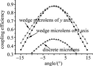
Figure 5. Relationship between coupling efficiency and angular error of different structures
两种耦合结构角向误差差异不大。分立式耦合结构角向误差分析与微透镜耦合结构x轴与y轴角向误差变化曲线较相似,都关于中心光轴对称。但微透镜直接耦合结构的能量是分立式耦合结构的两倍。
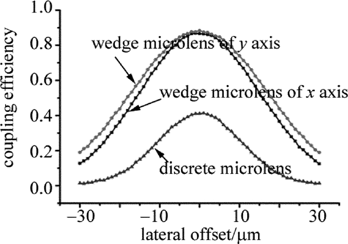
楔形截顶微透镜耦合结构与分立式耦合结构横轴误差如图 6所示(由于微透镜端面x与y方向不对称,在分析微透镜耦合结构横向误差时分别对x方向和y方向进行测试)。

Figure 6. Relationship between coupling efficiency and lateral error of different structures
对微透镜耦合结构和分立式透镜耦合横向误差对比可知,在两种最佳耦合结构的基础上,且每偏离中心1μm距离耦合效率都有下降。微透镜耦合结构的x轴和y轴的横向误差曲线-10μm~10μm处其耦合效率始终大于60%,且变化较为平缓;分立式透镜耦合整体耦合效率较低,在-10μm~10μm处耦合效率降低至25%。
楔形截顶微透镜耦合结构与分立式耦合结构左右纵向误差如图 7所示。
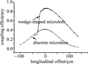
Figure 7. Relationship between coupling efficiency and longitudinal error of different structures
微透镜耦合结构的变化规律在端面两侧并不对称,原因之一是激光光束能量分布并沿z轴并不是呈对称分布。增大z值,光束分散,耦合光功率下降,由于有端面微透镜对光束进行整合,耦合效率下降缓慢,减小z值时,其光束集中,有限尺寸内其耦合效率变化不明显,随着z值进一步减小,需要整合的光束透过微透镜平面直接进入光纤,这部分光束不能满足耦合条件,且数量大幅增加,耦合效率下降明显;而分立式耦合结构中,其耦合效率变化就明显对称;对比之下,微透镜耦合结构纵向误差变化较平缓。
-
通过横向、纵向和角向误差分析方案对DFB激光器与光纤直接耦合、分立式耦合的耦合距离和效率进行分析。提出了一种基于DFB激光器与楔形截顶光纤微透镜的直接耦合结构,仿真实验表明,楔形截顶光纤微透镜耦合结构的横向、纵向、角向容忍度均高于传统分立式耦合结构,耦合效率可达84.40%。本文中的结构同时具有加工方便、封装体积小的优势。
基于DFB激光器的楔形截顶光纤微透镜耦合结构
Coupling structure of truncated wedge-shaped optical microlens based on DFB laser
-
摘要: 为了解决分布式反馈激光器的光发射次模块耦合封装中存在最大耦合效率局限的问题, 采用楔形截顶光纤微透镜代替分立式透镜的直接耦合的方法, 得到斜面倾角0.6rad、耦合距离60μm、半宽度15μm的楔形截顶光纤端面模型。在此基础上与分立式和直接耦合进行对比, 讨论了纵向、横向和角度偏移误差。结果表明, 纵向耦合距离在-21.45μm~56.79μm, 角向耦合角度在-8.3°~8.5°, 耦合效率始终大于70%;结构整体容忍度较高, 耦合效率达84.40%。该研究可为下一代分布式反馈激光器的次发射模块耦合封装器件提供新的解决方案。Abstract: In order to overcome the limitation of maximum coupling efficiency in the coupling package of optical emission sub-modules of distributed feedback laser lasers, the wedge-shaped truncated optical fiber microlens was used to replace the discrete lens in direct coupling scheme.A wedge-shaped truncated end-face model with inclined angle of 0.6rad, coupling distance of 60μm and half-width of 15μm was obtained. On this basis, compared with discrete and direct coupling, longitudinal, transverse and angular migration errors were discussed.The results show that, when longitudinal coupling distance is -21.45μm~56.79μm and angular coupling angle ranges from -8.3°~8.5°, the coupling efficiency is always greater than 70%. The overall tolerance of structure is high and the coupling efficiency is 84.40%.This research can provide a new solution of secondary emission module of coupling package device for the next generation distributed feedback lasers.
-
Figure 2. Light field distribution characteristics of DFB laser
a—far-field light distribution map b— relationship between spot radius and propagation distance of fast and slow axes
Figure 5. Relationship between coupling efficiency and angular error of different structures
Figure 6. Relationship between coupling efficiency and lateral error of different structures
Figure 7. Relationship between coupling efficiency and longitudinal error of different structures
Table 1. Comparison of coupling distance and coupling efficiency of three structures
structure direct coupling discrete coupling wedge shaped microlens distance 60μm 4.8mm 60μm optical power/W 1.037 1 1.019 ejection power/W 0.277 0.407 0.86 coupling efficiency/% 26.71 40.7 84.40  下载: 导出CSV
-
[1] XING J, RONG W, SUN D, et al. Extrusion printing for fabrication of spherical and cylindrical microlens arrays[J]. Applied Optics, 2016, 55(25):6947. doi: 10.1364/AO.55.006947 [2] ZOU H, HUANG H, CHEN S, et al. Laser printed fiber microlens for fiber-diode coupling by direct laser writing.[J]. Applied Optics, 2014, 53(36):8444-8448. doi: 10.1364/AO.53.008444 [3] YEH S M, HUANG S Y, CHENG W H. A new scheme of conical-wedge-shaped fiber endface for coupling between high-power laser diodes and single-mode fibers[J]. Journal of Lightwave Technology, 2005, 23(4):1781-1786. doi: 10.1109/JLT.2005.844511 [4] MUKHOPADHYAY S, GANGOPADHYAY S, SARKAR S N. Coupling of a laser diode to monomode elliptic core fiber via upside down tapered microlens on the fiber tip: Estimation of coupling efficiency with consideration for possible misalignments by ABCD matrix forma-lism[J]. Optik—International Journal for Light and Electron Optics, 2010, 121(2):142-150. doi: 10.1016/j.ijleo.2008.06.001 [5] DAS B, MAITI A K, GANGOPADHYAY S. Excitation of single-mode circular core parabolic index fiber by laser diode via upside down tapered hemispherical microlens on the tip of the fiber: Estimation of coupling efficiency by application of ABCD matrix formalism[J]. Journal of Optical Communications, 2014, 35(2):95-100. [6] LU Y K, TSAI Y C, LIU Y D, et al. Asymmetric elliptic-cone-shaped microlens for efficient coupling to high-power laser diodes[J]. Optics Express, 2007, 15(4):1434-1442. doi: 10.1364/OE.15.001434 [7] HAN Y B. Research on fiber laser microlens coupling technology of semiconductor laser [D]. Changchun: Changchun University of Science and Technology, 2008: 71-86(in Chinese). [8] WU C C, TSENG Y D, KUO S M, et al. Fabrication of asperical lensed optical fibers with an electro-static pulling of SU-8 photoresist[J]. Optics Express, 2011, 19(23):22993-22998. doi: 10.1364/OE.19.022993 [9] CHEN J L, SHEEN M T, HSIEH W H, et al. New scheme of hyperboloid microlens for high-average and high-yield coupling, high-power lasers to single-mode fibers[J]. Journal of Lightwave Technology, 2013, 31(11):1681-1686. doi: 10.1109/JLT.2013.2256337 [10] LIN C H, LIU C N, LEI S C, et al. Micro-hyperboloid lensed fibers for efficient coupling from laser chips[J]. Optics Express, 2017, 25(20):24480-24485. doi: 10.1364/OE.25.024480 [11] ZHANG L, ZENG Y, CHEN G Q, et al. Study on energy distribution characteristics of wedge-shaped micro/nano fiber[J]. Laser Technology, 2015, 39(5):689-693(in Chinese). [12] YIN Zh, LIU G D, LIU B G, et al. Research on the objective function of spatial light modulator-based output spot focusing for multimode fiber[J]. Chinese Journal of Lasers, 2015, 42(7):0705003(in Chinese). doi: 10.3788/CJL201542.0705003 [13] YIN Z Y, WANG Y F, YIN S Y, et al. Design of semiconductor laser shaping system based on hyperbola substrate microlens array[J]. Chinese Journal of Lasers, 2013, 40(6):0602016(in Chinese). doi: 10.3788/CJL201340.0602016 [14] HASHIM A, BAMIEDAKIS N, BEALS I V J, et al. Cost-effective 10Gb/s polymer-based chip-to-chipoptical interconnect[J]. The Institution of Engineering and Technology, 2012, 6(3): 140-146. [15] LIM K S, PARK H J. Fully passive-alignment pluggable compact parallel optical interconnection modules based on a direct-butt-coupling structure for fiber-optic applications[J]. Optical Engineering, 2016, 55(2):026107. doi: 10.1117/1.OE.55.2.026107 [16] WANG K L, LIU Y L, CHEN H B, et al. Linewidth measurement of DFB laser with frequency shift delay and heterodyne method[J]. Laser Technology, 2018, 42(5):633-637(in Chinese). [17] YIN G, LOU S, LI Q, et al. Theory analysis of mode coupling in tilted long period fiber grating based on the full vector complex coupled mode theory[J]. Optics & Laser Technology, 2013, 48(6):60-66. -

 点击查看大图

图(7) / 表(1)
计量
- 文章访问数: 4177
- HTML全文浏览量: 2724
- PDF下载量: 21
- 被引次数: 0
