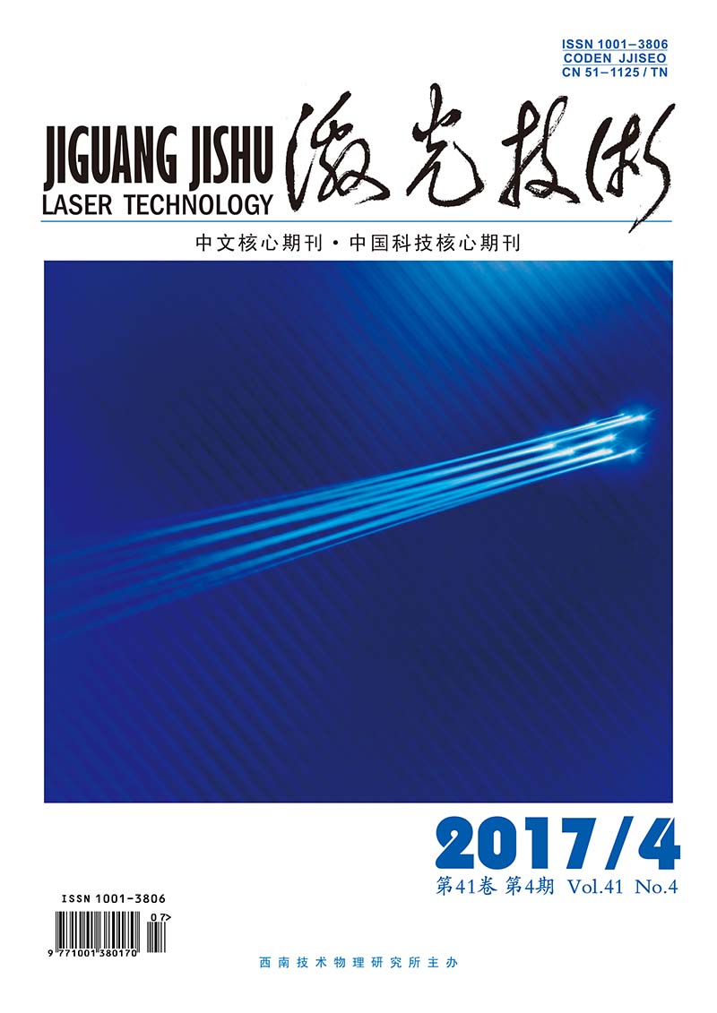
Advanced Search

ISSN1001-3806 CN51-1125/TN Map

Volume 41 Issue 4
May  2017
Article Contents
Turn off MathJax

Citation:

Measurement of laser spot center position based on sub pixel positioning technology

  • Corresponding author: LI Xinghua, li.xinghua@126.com
  • Received Date: 2016-09-23
    Accepted Date: 2016-10-24
  • In order to overcome the shortcomings of traditional subpixel location algorithm, such as weak anti-jamming ability, poor positioning accuracy, and difficulty in software realization, and improve the center location accuracy of laser spot, the method of curve fitting was used and a high-precision positioning measurement method of small spot size was proposed. After theoretical analysis and experimental verification, the error of center-of-mass extraction is controlled within 0.1pixel. The results show that the image centroid measurement method reduces the noise interference effectively and enhances the anti-noise performance. Compared with the traditional algorithm, the error is smaller.
  • 加载中
  • [1]

    ZHANG Q J, ZHAO Y H. Measurement method of laser spot center based on weight interpolation algorithm [J]. Laser & Infrared, 2016, 46(1):81-84(in Chinese).
    [2]

    CHEN H, YANG Zh H, GUO Q, et al. Research of the high precision laser spot center location algorithm [J]. Transactions of Beijing Institute of Technology, 2016, 24(2):181-185(in Chinese).
    [3]

    ZHOU J B, FAN Y, XIAO D Ch. High accuracy real - time detection of spot center based on machine vision [J]. Microcomputer Information, 2009, 25(16):122-123(in Chinese).
    [4]

    WANG Zh J, ZIOU D, ARMENAKIS C, et al. A comparative analysis of image fusion methods[J]. IEEE Transactions on Geoscience & Remote Sensing, 2012, 43(6):1391-1402.
    [5]

    ZHOU H F, REN P Sh. Study on the processing of spot image and its accuracy in optical measurement [J].Journal of Jixi University, 2014, 17(5):61-63(in Chinese).
    [6]

    WANG Y Q. Research on key technology of laser measuring instrument[D].Hangzhou: Zhejiang University of Science and Technology, 2013: 45-50(in Chinese).
    [7]

    LI Q. Research on sub-pixel location technology of laser spot center [J]. Chinese Journal of Quantum Electronics, 2012, 29(1):58-62(in Chinese).
    [8]

    WANG Ch Y. Research on key technologies of light stripe in laser measurement [D].Changchun: Jilin University, 2014: 23-28(in Chinese).
    [9]

    CHEN M L. Parameters determination method in three-coordinate laser measurement technical specification [J]. Laser Technology, 2014, 38(1):109-113(in Chinese).
    [10]

    PAN B, YANG G Q, LIU Y. Study on optimization threshold of centroid algorithm [J]. Optics and Precision Engineering, 2008, 16(9): 1787-1792(in Chinese).
    [11]

    LIU J, LI M Zh, ZHAN G W, et al. Parameters determination method in three-coordinate laser measurement technical specification [J]. Laser Technology, 2015, 39(1):140-144(in Chinese).
    [12]

    LIU L Sh, ZHANG Y, LU H Q, et al. A fast sub-pixel edge detection method for images [J]. Journal of Optoelectronics·Laser, 2005, 16(8):993-996(in Chinese).
    [13]

    HUANG H Y, LI G, HE Y Q, et al. Algorithm for laser spot precise locating in omni-directional laser detecting system [J]. Laser & Infrared, 2010, 40(11):1224-1228(in Chinese).
    [14]

    WANG X, TAN J P, QUAN L Y, et al. Fast and precise location method of the laser beam center point in complex industrial environment [J]. Journal of Hunan University(Natural Sciences Edition), 2012, 39(12):43-49(in Chinese).
    [15]

    WOODS N A, GALATSANOS N P, KATSAGGELOS K K. Stochastic methods for joint registration, restoration, and interpolation of multiple undersampled images[J]. IEEE Transactionson Image Processing, 2006, 15(1):201-213.
  • 加载中
通讯作者: 陈斌, bchen63@163.com
  • 1. 

    沈阳化工大学材料科学与工程学院 沈阳 110142

  1. 本站搜索
  2. 百度学术搜索
  3. 万方数据库搜索
  4. CNKI搜索

Figures(3) / Tables(1)

Article views(2778) PDF downloads(16) Cited by()

Proportional views

Measurement of laser spot center position based on sub pixel positioning technology

    Corresponding author: LI Xinghua, li.xinghua@126.com
  • 1. State Key Laboratory of Precision Measuring Technology and Instruments, Tianjin University, Tianjin 300072, China
  • 2. Beijing Spacecraft Overall Design Department, Beijing 100094, China

Abstract: In order to overcome the shortcomings of traditional subpixel location algorithm, such as weak anti-jamming ability, poor positioning accuracy, and difficulty in software realization, and improve the center location accuracy of laser spot, the method of curve fitting was used and a high-precision positioning measurement method of small spot size was proposed. After theoretical analysis and experimental verification, the error of center-of-mass extraction is controlled within 0.1pixel. The results show that the image centroid measurement method reduces the noise interference effectively and enhances the anti-noise performance. Compared with the traditional algorithm, the error is smaller.

引言
  • 光斑中心定位是光学测量中的关键技术之一,特别是针对摄影图像小尺寸光斑中心的定位问题,可以为其提供更加精确的数据、科学的算法[1]。本文中基于亚像素定位技术的激光光斑中心定位测量的课题实践,研究的对象是光斑图像,而光斑质心是其核心特征。在研究设计上,相机镜头在转动后,对激光光斑质心位置进行提取、确认。关于点状光斑的质心位置定位方法,国内外最常采用的分为两类:一类是基于灰度的方法; 另一类是基于边缘的方法。基于灰度的方法,指利用目标的灰度来分布信息,主要适用于半径较小且灰度分度均匀的光斑图像;基于边缘的方法,是利用目标的边缘形状信息,适用于半径相对较大的光斑图像。本文中以小尺寸光斑图像作为对象,采用基于灰度的质心位置定位方法[2]

1.   亚像素定位技术
  • 亚像素指面阵摄像机的成像面以像素为最小单位,摄像机在拍摄的过程中,将物理世界中连续的图像进行离散化处理,处理完成后,传输到成像面上的每一个像素点,分别代表着附近的颜色。从宏观的角度来看,成像面上所有的像素点连在一起,人们肉眼无法观察到[3],传统的相机硬件装置上传感器也无法将其检测出来。从微观视角来观察,它们一直都是存在着的,这种无限小的东西,将其称之为“亚像素”。在关于亚像素定位的研究层面,一般都是通过特定化的软件将其近似地表现、计算出来[4]

  • 从技术理论的层面看,小尺寸光斑成像应聚集在一个像元内,在实际操作的过程中,经常与理论出现偏差。以安装某互补金属氧化物半导体(complementary metal oxide semiconductor, CMOS)摄像芯片的相机为例[5],在实际拍摄中,单个像素的定位精度无法满足测量的要求。针对这种情况,一般在光斑图像质心位置定位的时候,大多采用散焦方法,使得光斑成像扩散到多个像素。完成后,只需要利用中心定位算法就可以得到亚像素级的定位精度。

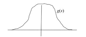
  • 关于光斑图像的灰度分布方法的应用,是光学系统的点扩展函数表达,通过(2维)高斯分布函数可以表示为:

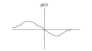
    式中,A表示光斑图像像素点的总能量(本文中以小尺寸图像为主); (x, y)表示高斯分布函数中心点位置的坐标; σ表示高斯函数的方差,对应的是光斑弥散半径的大小数值; B为常数, g(x)表示函数坐标x方向的1维高斯分布函数; g(y)表示y方向的1维高斯分布函数。

    x方向坐标为例,图 1中呈现的是理想光斑x方向的能量分布函数曲线关系表达。图 2呈现的是x值为极大值点的时候,该x点处位置的1阶导数为0,并且临近区域呈递减状态。

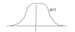
    Figure 1.  Energy distribution function of ideal spot in x direction

    Figure 2.  The 1st order derivative of x direction

2.   亚像素光斑中心计算
  • 引入电荷耦合器件(charge coupled device, CCD)的光学成像原理[6],在激光光斑中心位置测量中,CCD激光光斑图像中心精确定位是最核心的测试目标。输出的结果为该图像的灰度值。表示为:

    式中,f(i, j)表示像素的输出值,即灰度值; g(x, y)表示连续图像的光强分布。在针对采样数据测量处理分析上,其结果是一个以灰度值为数值的离散矩阵。

    关于亚像素光斑中心位置的计算、确认,高斯分布函数x方向1阶导数,1阶导数零交叉准确定位后,光斑图像质心位置得以确定,记为(x0, y0)坐标点,其临域内确定光斑亚像素中心的坐标点,表示为(x, y)。

    本次实验样本利用CCD采集,在采集光斑图像时,会遇到一些因素的限制[7]。比如,图像采集卡的有效位数一般都是8位数,当光强比较大,或者CCD曝光时间相对过长的时候,容易导致数据饱和,灰度值超过一定的数值。在这种情况下,光斑光强往往无法真实反映出来。与此同时,单纯地进行高斯拟合,也容易造成一定的误差。为了更好地表现出这种预期中的效果,可以将两种算法融合[8]。如此一来,既可以满足高斯拟合过程中剔除这些饱和点,同时对于光斑半径小、有效点少的光斑图像,充分利用x方向上从属于同一光斑的3个像素点的灰度值,建立有效的方程表达组来更精准地求解出x值。

    首先提取、假设3个点,3个点的横坐标分别记为x1x2x3,这3个横坐标点对应的灰度值分别表示为g(x1), g(x2), g(x3),从而得出方程组:

    式中,C为共同常量。

    同理,继续提取并假设3个纵坐标点,在假设的中心点(x0, y0)所在的y方向上,提取从属于同一光斑的3个像素点,分别记为y1, y2y3,从而得出:

    将上述(3)式和(4)式合并计算,得出方程组:

3.   仿真计算结果分析
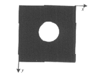
  • 基于亚像素定位技术,提出了一种小尺寸光斑中心的高精度测量算法,并且融合了曲线拟合的高斯分布测量方法[9]。在仿真测试实验设计层面上,实验中所需的硬件环境选用了core 2高性能处理器[10],内存为2GB, 如图 3所示。像素点的灰度值设置为0或者255,预处理环节,进行二值化处理,采样图像呈现为(明显)黑白效果,对于阈值的设定[11],以实际反映出的图像整体/局部特征作为标准依据,再结合着曲线拟合来对各像素点进行精确定位。

    Figure 3.  Image of laser spot

    表 1是生成的5个仿真图像(已知中心点)激光光斑中心定位的实际情况。

    the centroid position small spot size algorithm fusion curve fitting algorithm
    center absolute error center absolute error
    (81.0, 81.0) (81.49, 81.48) (0.49, 0.48) (81.08, 81.07) (0.08, 0.07)
    (81.1, 81.1) (81.48, 81.51) (0.38, 0.41) (81.06, 81.18) (0.04, 0.08)
    (81.2, 81.2) (81.56, 81.62) (0.36, 0.42) (81.24, 81.30) (0.04, 0.10)
    (81.3, 81, 3) (81.71, 81.80) (0.41, 0.50) (81.40, 81.38) (0.10, 0.08)
    (81.4, 81.4) (81.90, 81.99) (0.50, 0.59) (81.50, 81.46) (0.10, 0.06)

    Table 1.  Positioning results of laser spot center based on sub pixel positioning/pixel

    表 1中亚像素定位激光光斑中心定位结果的数据统计中可以观察到,联合算法下的光斑图像质心位置的计算,其绝对误差更小[12]。可以看到,改进前绝对误差依次是(0.49, 0.48), (0.38, 0.41), (0.36, 0.42), (0.41, 0.50), (0.50, 0.59),算法改进后绝对误差依次是(0.08, 0.07), (0.04, 0.08), (0.04, 0.10), (0.10, 0.08), (0.10, 0.06)。前者误差像素高达0.4pixel~0.6pixel,后者误差像素被控制在0.1pixel之内,效果非常明显。

4.   结论
  • 针对小尺寸光斑图像质心的测量和计算,常选用的方法有质心法、Hession矩阵法、高斯拟合法。质心法运算速度相对更快[13],定位更加精确。但却存在一个较大的缺陷,即抗噪声能力差。因此,实际应用中,必须对其进行改进,比如采用带阈值的质心算法。高斯拟合法就具备这样一种优势[14],本次实验研究在高斯曲线拟合融合基础上,提出了一种小尺寸光斑图像亚像素定位测量方法。由最终的实验仿真结果得出,5个仿真图像在改进前,绝对误差依次是(0.49, 0.48), (0.38, 0.41), (0.36, 0.42), (0.41, 0.50), (0.50, 0.59);算法改进后,绝对误差依次是(0.08, 0.07), (0.04, 0.08), (0.04, 0.10), (0.10, 0.08), (0.10, 0.06)。前者误差像素高达0.4pixel~0.6pixel,后者误差像素被控制在0.1pixel之内,效果非常明显。该结果充分表明了,在无噪声影响的空间环境情况下,基于亚像素定位技术的光斑图像质心算法[15],可以将定位误差控制在0.1pixel范围内,很好地保证了光斑中心的高精度定位。

Reference (15)

Catalog

    /

    DownLoad:  Full-Size Img  PowerPoint
    Return
    Return