Advanced Search

ISSN1001-3806 CN51-1125/TN Map

Volume 41 Issue 4
May  2017
Article Contents
Turn off MathJax

Citation:

3-D position measurement algorithm based on laser displacement sensors

  • Corresponding author: LI Zongfeng, lzfeng@csu.ac.cn
  • Received Date: 2016-09-20
    Accepted Date: 2016-11-09
  • In order to realize the design of feedback control circuit of space micro gravity active vibration isolation system, 6 laser displacement sensors were used to measure the displacements of 3 orthogonal positioning surfaces of vibration isolation platform. 3-D position and attitude were solved. And the derivation process was also given. The method was verified by numerical simulation and experimental test. The source of error and its influence on the result of calculation were analyzed. The relationship between error influence factors and calculation error was given. The results show that this algorithm can accurately calculate the 3-D position and attitude of a vibration isolation platform. The theoretical calculation error is less than 30μm. This research has some practical value and prospects for the design of feedback control loop based on displacement measurement.
  • 加载中
  • [1]

    LI Z F. 3-D position measurement of active vibration isolation system under space microgravity[J]. Journal of Astronautics, 2010, 31(6):1625-1630(in Chinese).
    [2]

    DAI B, SUN Zh B, WANG F L, et al. Design of measurement and control system of position of electrostatic levitation based on PSD[J]. Transducer and Microsystem Technologies, 2015, 34(3):97-99(in Chinese).
    [3]

    ZHOU M L, BAI Z W. Design of the laser displacement measurement system based on 2D-PSD[J]. Foreign Electronic Measurement Technology, 2015, 34(2):64-66(in Chinese).
    [4]

    CHANG W K, LI E, YANG G D, et al. Close-up measurement for 3-D position of power transmission line using stereo vision[J]. Journal of Huazhong University of Science and Technology (Natural Science Edition), 2015, 43(s1):144-147(in Chinese).
    [5]

    ZHANG H B, LIU Sh R, ZHANG B T. Binocular vision position algorithm using hue-saturation histogram back-project combined with feature point extraction[J]. Control Theory & Applications, 2014, 31(5):614-632(in Chinese).
    [6]

    FUJIYOSHI H, SHIMIZU S, NISHI T, et al. Fast 3-D position measurement with two unsynchronized cameras[C]// IEEE International Symposium on Computational Intelligence in Robotics and Automation, 2003. New York, USA: IEEE, 2003: 1239-1244.
    [7]

    SHAN L, KONG M, HOU R, et al. A three-dimensional coordinate measuring method based on ultrasonic sensor[J]. Transducer and Microsystem Technologies, 2013, 32(6):123-125(in Chinese).
    [8]

    ZHAO Y L, XU Zh L, LI K D. Laser micro-displacement measurement system based on CCD[J]. Laser Technology, 2003, 27(1):73-75(in Chinese).
    [9]

    ZHOU Y, ZHAO H, TAO W, et al. Adaptive control method for imaging parameters of image sensor in laser triangulation displacement meagsurement[J]. Laser Technology, 2010, 34(5):628-631(in Chinese).
    [10]

    LIU Y, WANG Y. Present status and thrend of technical development of displacement sensor[J]. Techniques of Automation and Applications, 2013, 32(6):76-80(in Chinese).
    [11]

    FENG J Y, FENG Q B, KUANG C F. Present status of high precision laser displacement sensor based on triangulation[J]. Journal of Applied Optics, 2004, 25(3):33-36(in Chinese).
    [12]

    FENG Zh J. Principle of mechanical manufacturing engineering [M]. Beijing:Tsinghua University Press, 2008:209-211(in Chinese).
    [13]

    WU J F, WANG W, CHEN Z Ch. Study on the analysis for error in triangular laser measurement and the method of improving accuracy[J]. Journal of Mechanical & Electrical Engineering, 2003, 20(5):89-91(in Chinese).
    [14]

    CHEN H, LÜ Ch, CHE Y, et al. Analysis on the object surface tilt effect on the measurement error of laser triangulation method [J]. Journal of Changchun University of Science and Technology (Natural Science Edition), 2015, 38(1):17-20(in Chinese).
    [15]

    YU P Zh. The analysis of error and study on improvement measures in the detection of displacement by laser triangulation [D]. Changchun: Changchun University of Science and Technology, 2013: 13-27(in Chinese).
    [16]

    LI Q Y. Principle of numerical calculation [M]. Beijing: Tsinghua University Press, 2000:167-168(in Chinese).
  • 加载中
通讯作者: 陈斌, bchen63@163.com
  • 1. 

    沈阳化工大学材料科学与工程学院 沈阳 110142

  1. 本站搜索
  2. 百度学术搜索
  3. 万方数据库搜索
  4. CNKI搜索

Figures(5) / Tables(6)

Article views(3140) PDF downloads(413) Cited by()

Proportional views

3-D position measurement algorithm based on laser displacement sensors

    Corresponding author: LI Zongfeng, lzfeng@csu.ac.cn
  • 1. Technology and Engineering Center for Space Utilization, Chinese Academy of Sciences, Beijing 100094, China
  • 2. University of Chinese Academy of Sciences, Beijing 100049, China

Abstract: In order to realize the design of feedback control circuit of space micro gravity active vibration isolation system, 6 laser displacement sensors were used to measure the displacements of 3 orthogonal positioning surfaces of vibration isolation platform. 3-D position and attitude were solved. And the derivation process was also given. The method was verified by numerical simulation and experimental test. The source of error and its influence on the result of calculation were analyzed. The relationship between error influence factors and calculation error was given. The results show that this algorithm can accurately calculate the 3-D position and attitude of a vibration isolation platform. The theoretical calculation error is less than 30μm. This research has some practical value and prospects for the design of feedback control loop based on displacement measurement.

引言
  • 空间高微重力主动隔振系统是针对未来我国空间科学实验载荷微重力环境需求而研制的一套支撑平台。它采用磁悬浮主动隔振技术,实现高于目前“神舟”系列飞船上的微重力水平,为空间科学实验载荷提供更好的实验环境保障。为了实现理想的隔振性能,需要对载荷进行位置和姿态的测量,并进一步得到其线加速度和角加速度,以便设计主动隔振反馈控制回路,同时控制浮子免于碰撞定子内壁,保障载荷的微重力水平不被破坏,达到低频隔振的目的[1]

    精密3维位置测量技术一直是测量技术领域研究的热点,被广泛应用于工业自动化加工和工业检测等诸多工业场合。常见的3维位置测量方法有基于位置敏感探测器(position sensitive detector,PSD)的位置测量方法[1-3],其通过在待测量物体上安装多个发光管,利用多个发光管的光点在与其对应的2维PSD上的位置变化来解算待测物体的3维位置,其优点在于能够同时解算出待测物体的3维位置和姿态且测量的绝对误差较小,为±20μm,而缺点则由于需要在待测物体上安装发光管及供电线缆,线缆会对待测物体的运动产生一定干扰;基于图像视觉的位置测量方法[4-6],其通过图像视觉系统获取待测量物体的左右视图,通过对左右视图的特征提取得出待测量物体的3维位置信息,其优点在测量过程中不需要对待测量物体进行处理,而缺点则是求解的计算量较大并且测量的绝对误差较大,为±1mm;基于超声波传感器的测量方法[7],其通过在待测物体上安装超声波发射端,同时在环境中布置多个超声波接收端,通过测量发射端到每个接收端的距离来确定待测量物体的位置,其优点在于待测量物体可以有较大的运动范围,而缺点则同样是测量的绝对误差较大,为±5mm。以上多数方法不能够很好地实现对微重力环境下物体微小位置和姿态变化的测量。

    三角测量法是一种位移测量方法,其最大优点是非接触性测量。随着激光器的诞生及新的光电扫描技术与阵列型光电探测器的发展,计算机控制与数据处理使这种传统的方法有了很多新的进展和应用。其中激光位移传感器作为一种非接触式的精密激光测量系统,具有适应适应性强、速度快、精度高等特点,适用于检测各种回转体、箱体零件的尺寸和形位误差[8-10]。本文中将给出一种使用基于三角测量法的激光位移传感器[11],对于隔振平台的位置及其姿态进行解算的方法,用于主动隔振系统中基于位移测量的反馈控制回路设计。

1.   位移测量原理
  • 对于一个刚体,其在空间中有6个自由度(3个平动自由度,3个转动自由度),则可以通过测量物体到空间6个基准点的距离来确定物体的位置,即六点定位原理[12]

    对于一个立方体,可以首先通过3个不在同一直线上的基准点定位其中的一个平面,再利用两个测点定位一个与已确定平面正交的平面,最后在利用一个测点确定一个与之前两个平面都正交的平面。此时立方体的位置将完全确定。

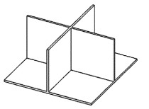
    而对于一般形状的物体,无法找到物体上3个互相正交的平面,这时可以在物体上安装如图 1所示3个互相正交的定位片,如此只要定位了3个定位片,待测物体的位置就完全确定。同时对于定位片,还可以对其表面做一定的处理,使其更好地适应激光位移传感器的测量[13]

    Figure 1.  Structure of positioning piece

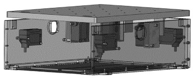
    测量系统的设计如图 2所示。为了定位上方隔振平台的3维位置和姿态,在其底面上安装图 1中所示的定位片,并在其下方中合理的放置6个激光位移传感器,对于测量同一个定位片的激光位移传感器,将其尽量分散放置,使其测量点尽量分散从而提高解算精度。同时由于激光位移传感器的测量范围有限,需要将定位片和激光位移传感器始终保持在有效的测量距离内。

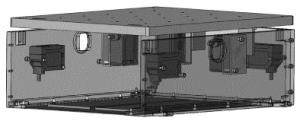
    Figure 2.  Installation position of laser displacement sensor

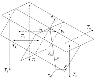
  • 首先确定测量所使用的坐标系,如图 3所示。先将3个定位片的被测量平面与对应的激光位移传感器的测量方向正交,将此时的3个被测平面形成的直角坐标系(待测物体的本体坐标系xbybzb)作为测量的基准坐标系xyz,坐标原点是此时3个被测平面的交点。其中点T1~T6为6个激光位移传感其的位置,其分别测量箭头所指位置的位移; rSE为待测物体基准点(3个被测平面的交点)在测量基准坐标系中的位置矢量。

    Figure 3.  Definition of coordinate system

    此时待测物体的基准点的坐标和物体的方向余弦矩阵分别为:

    然后根据每个激光位移传感器的安装位置,确定其激光点在测量坐标系中两个非测量方向上的坐标值,由于测量点的两个非测量坐标值与激光位移传感器的对应坐标相同,如此就可以测得6个测点的完整的3个坐标值。并将此时的激光位移传感器的状态作为位移值的测量基准。

    当物体的位置发生变化后,假设6个激光位移传感器的读数分别为v1~v6,同时假设初始状态与测量的基准坐标系z轴正交的定位平面有3个测点,此时对应激光位移传感器的读数分别为v1, v2, v3,则设位移后该平面的方程为:

    代入测点的坐标值:

    可以求得与测量的基准坐标系z轴正交的平面所在的几何平面的方程。

    同理假设初始状态与测量的基准坐标系y轴正交的定位平面有2个测点,此时对应激光位移传感器的读数分别为v4, v5,同时其与以上所求的平面正交,设其所在几何平面的方程为:

    根据定位平面的正交关系:

    代入测点的坐标值,联立得到:

    可以求得与测量的基准坐标系y轴正交的平面所在的几何平面的方程。

    同理假设初始状态与测量坐标系x轴正交的定位平面有1个测点,此时对应激光位移传感器的读数分别为v6,同时其与以上所求的两个平面正交,设其所在几何平面的方程为:

    使用和前面类似的方法可以得到:

    可以求得到与测量的基准坐标系x轴正交的平面所在的几何平面的方程。

    联立以上3个平面的方程,可以得到3个平面的交点的坐标,即待测物体参考点的位置,即:

    根据以上的计算待测物体的本体坐标系的3个基向量$\overrightarrow {{\mathit{\boldsymbol{e}}_1}} , \overrightarrow {{\mathit{\boldsymbol{e}}_2}} , \overrightarrow {{\mathit{\boldsymbol{e}}_3}} $分别为:

    式中,ijk为测量基准坐标系的3个坐标基向量; e1e2e3为待测物体的本体坐标系的3个基向量在测量坐标系下的坐标。

    则其方向余弦矩阵为:

2.   测量仿真实验
  • 假设待测物体以如下的规律运动:

    式中,t为运动时间; xcyczc为待测物体基准点在测量的基准坐标系中的坐标; θxθyθz分别为待测物体绕xyz坐标轴的欧拉角(xyz顺序)。

    测量中激光位移传感器按照表 1中的位置进行安装。

    laser displacement sensor number x/m y/m z/m
    1 0.1129 -0.2087 0.0000
    2 -0.0846 -0.2087 0.0000
    3 0.1259 0.0058 0.0000
    4 0.1079 0.0000 -0.0270
    5 -0.0676 0.0000 -0.0270
    6 0.0000 -0.0100 -0.0270

    Table 1.  Installation position of laser displacement sensor

    根据(13)式中给出的待测物体的实际位置,可以确定3个定位平面所在几何平面的方程,将表 1中激光位移传感器的安装位置分别代入对应的方程就可以预测出6个激光位移传感器的读数,然后再利用预测的读数、使用上述方法解算出待测物体的位移和欧拉角,如图 4图 5所示。其中δxc,δyc,δzc分别为待测物体基准点坐标误差,δθx,δθy,δθz分别为3个欧拉角误差。

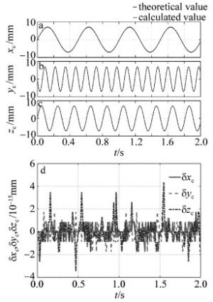
    Figure 4.  Displacement of x, y, z axes and coordinate error of the measured object

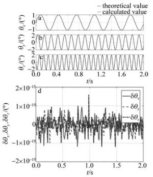
    Figure 5.  Euler angle of x, y, z axes and calculation error of the measured object

    可以看出, 由于没有考虑外界误差因素的影响,理论值与解算值几乎完全相同,这里的误差主要来自于解算过程中计算机的舍入误差。

3.   误差分析
  • 测量误差主要来源于位移计安装位置坐标的测量误差,位移计安装方向的偏差导致的测量偏差,位移计自身的测量误差,测量平面的粗糙度以及倾斜程度,以及3个测量平面不完全互相正交带来的测量偏差[13-15]

    其中使用的激光位移传感器自身的测量误差在10μm量级,测量平面的不平整程度一般要小于这一量级,属于误差中相对最小的部分。激光位移传感器的安装位置误差和安装方向偏差导致的测量误差相对要更加明显一些。这里假设位移计安装位置的测量误差在100μm的量级。

    对于以下形式的线性方程组:

    式中,A为系数矩阵,x为解向量,b为右端向量。

    由求解误差与方程组误差的关系[16]

    式中,δA,δx,δb分别为误差系数矩阵、误差解向量和误差右端向量。

    可以看出,求解的误差的放大主要取决于方程组的条件数,同时根据实际的测量情况,即激光位移传感器测量值精度在10μm量级,测量的位移值在10mm量级,安装位置坐标在10cm量级。有:

    本文中用符号~表示此符号两边的表达式为同一量级。

  • 根据表 1中激光位移传感其的安装位置,对应求解过程中的4个系数矩阵的条件数见表 2

    i cond (Ai) cond (Ai)/‖Ai
    1 31.92 10.64
    2 12.62 6.43
    3 1.07 1.04
    4 1 1

    Table 2.  Condition number of coefficient matrix

    对于方程组求解,求解的相对误差为:

    此即位移解算的相对误差在1%的级别。

    在测量仿真实验中引入如下激光位移传感器的安装位置误差,仿真得到的最大测量误差如表 3所示。

    installation error/mm -20 -10 -5 -1 1 5 10 20
    solving error/mm x1 0.47 0.23 0.12 0.023 0.023 0.12 0.23 0.47
    y1 0.22 0.11 0.05 0.011 0.011 0.05 0.11 0.21
    x2 0.46 0.23 0.12 0.02 0.02 0.12 0.23 0.46
    y2 0.23 0.12 0.06 0.011 0.011 0.06 0.12 0.23
    x3 0.19 0.10 0.05 0.01 0.01 0.05 0.09 0.19
    y3 0.09 0.05 0.02 0.005 0.005 0.02 0.05 0.09
    x4 0.29 0.14 0.07 0.01 0.01 0.07 0.14 0.29
    z4 0.15 0.08 0.04 0.008 0.008 0.04 0.08 0.15
    x5 0.44 0.22 0.11 0.02 0.02 0.11 0.22 0.44
    z5 0.23 0.12 0.06 0.012 0.012 0.06 0.12 0.23
    y6 0.70 0.35 0.18 0.04 0.04 0.18 0.35 0.70
    z6 0.70 0.35 0.18 0.04 0.04 0.18 0.35 0.70

    Table 3.  Error caused by installation error

    根据(15)式中给出的误差关系,其中由于安装误差导致的位置解算误差为:

    其中:

    则得到位置解算误差与安装位置误差的关系为:

    使用此关系估计的误差如表 4所示。可以看出, 预计的误差和仿真实验中的结果基本相当,同时由于使用了相对保守的误差估计,这里的预计的误差结果要高于表 3中仿真实验的结果。

    installation error/mm -20 -10 -5 -1 1 5 10 20
    estimated error/mm 1.40 0.70 0.35 0.07 0.07 0.35 0.70 1.40

    Table 4.  Installation error and the estimated error

    在测量仿真实验中引入如下激光位移传感器的自身元件误差,仿真得到的最大测量误差如表 5所示。

    component error/mm -1 -0.5 -0.1 -0.05 -0.01 0.01 0.05 0.1 0.5 1
    solving error/mm 1.81 0.88 0.19 0.09 0.014 0.017 0.10 0.20 0.82 1.87

    Table 5.  Error caused by component error

    根据(15)式中给出的误差关系,其中由于元件误差导致的位置解算误差为:

    其中:

    则得到位置解算误差与安装位置误差的关系为:

    使用此关系估计的误差见表 6。可以看出,估计的误差和仿真实验中的结果基本相当,同时由于使用了相对保守的误差估计,这里的预计的误差结果也要高于表 5中仿真实验的结果。

    component error/mm -1 -0.5 -0.1 -0.05 -0.01 0.01 0.05 0.1 0.5 1
    estimated error/mm 2.33 1.16 0.23 0.12 0.02 0.02 0.12 0.23 1.16 2.33

    Table 6.  Component error and the estimated error

    同时考虑安装误差和元件误差,位置解算误差与安装误差和元件误差的关系如下:

    如前面所述,激光位移传感器安装位置的测量误差在100μm的量级,激光位移传感器自身的测量误差在10μm量级,则根据(24)式解算的精度在±30μm的量级。

4.   结论
  • 通过合理地布置3个正交的定位片和6个激光位移传感器,能够对隔振平台的3维位置和姿态进行精确的解算,理论解算精度在±30μm的量级,同时也避免了在隔振平台上连接线缆而产生的干扰作用,其在微重力环境下实现3维位置测量要优于多数其它测量方法。对于空间高微重力主动隔振系统的位置姿态进行确定,从而进行基于位移测量的反馈控制回路设计有着较高的实用价值和发展前景。

Reference (16)

Catalog

    /

    DownLoad:  Full-Size Img  PowerPoint
    Return
    Return