Advanced Search

ISSN1001-3806 CN51-1125/TN Map

Volume 43 Issue 3
Mar.  2019
Article Contents
Turn off MathJax

Citation:

Effect of temperature gradient on cracks in laser cladding layer

  • Corresponding author: SUN Wenlei, sunwenxj@163.com
  • Received Date: 2018-06-22
    Accepted Date: 2018-07-11
  • In order to reduce cracks in cladding layers caused by large temperature gradient in laser cladding technology, preheated matrix in laser cladding process was used to reduce temperature gradient. The finite element model of multi-lap temperature field of laser cladding nickel-based metal powder on 45# steel substrate was established by using ANSYS software. The reliability of the model was verified by thermocouple temperature measurement. Temperature gradient of cladding layer on the edge of cladding layer during the cladding process and the effect of the preheating temperature of the substrate on temperature gradient of cladding layer were analyzed by the finite element model. The results show that the maximum temperature gradient is located at the edge of the bonding interface between the cladding layer and the substrate. It is an extreme condition for the solidification of the metal molten pool and causes the crack to be easily produced here. With preheating temperature of 200℃, the substrate preheating can significantly reduce the temperature gradient during the solidification process of the cladding layer, and the decrease of the temperature gradient is more obvious, which can effectively inhibit the crack generation. The combination of simulation and experiment provides a practical reference for the actual laser cladding manufacturing.
  • 加载中
  • [1]

    YAO J H. Laser surface modification technology and application[M]. Beijing: National Defense Industry Press, 2012:59-61(in Chinese).
    [2]

    LI Sh Y, TIAN X G, LI Ch B. Study on wear-resistance and scanning path of laser alloying on end cap working face[J]. Chinese Journal of Lasers, 2013, 40(2):0203004(in Chinese).
    [3]

    ZHANG J Y, QIU Ch J, HE Y W. Microstructure and properties of Fe-based laser cladding with different Ni content[J]. Surface technology, 2017, 46(6):221-225(in Chinese).
    [4]

    XU B Sh. Development status and prospect of green remanufacturing engineering[J]. Engineering Sciences, 2011, 13(1):4-10(in Chinese).
    [5]

    RONG L R. Laser cladding technology and application of[J]. Metal Processing, 2012, 63(15): 37-39(in Chinese).
    [6]

    ZHANG M L, NING G Q, LIU W J. Research and development on laser direct manufacturing metallic components[J]. Laser Technology, 2002, 26(5):388-391(in Chinese).
    [7]

    ZUO T Ch, CHEN H.21 century green manufacturing of laser manufacturing technology and application[J]. Journal of Mechanical Engineering, 2009, 45(10):106-110(in Chinese). doi: 10.3901/JME.2009.10.106
    [8]

    WANG D Sh, TIAN Z J, WANG J W, et al.A method of crack control in laser cladding process with changing power density distribution of laser beam[J]. Chinese Journal of Lasers, 2011, 38(1):0103004(in Chinese).
    [9]

    XU J L, LI ZH G, GUO H F, et al.Research progress of crack defect in laser cladding layer[J]. Hot Working Technology, 2013, 42(8):6-9(in Chinese).
    [10]

    WU D J, WU N, YANG Ch, et al.Numerical simulation of the preheating effect on temperature gradient in laser cladding Al2O3 ceramic[J]. Rare Metal Materials and Engineering, 2013, 42(10):2039-2042(in Chinese).
    [11]

    LI Zh G, PENG B.Crack formation mechanism and control methods for laser cladding coatings[J]. Materials Protection, 2016, 49(11):61-66(in Chinese).
    [12]

    WEI J L, YU A B, SHI Ch Ch, et al.Influence of process parameters on laser cladding crack defects[J]. Laser Journal, 2016, 37(4):7-10(in Chinese).
    [13]

    LIU H, YU G, HE X L, et al. Three-dimensional numerical simulation of transient temperature field and coating geometry in powder feeding laser cladding[J]. Chinese Journal of Lasers, 2013, 40(12):1203007(in Chinese).
    [14]

    ZHAO H Y, SHU F Y, ZHANG H T, et al. Numerical simulation on temperature field of laser cladding based on birth-death element method[J]. Transactions of the China Welding Institution, 2010, 31(5):81-84(in Chinese).
    [15]

    ZHANG J, SONG J L, LI Y T.Numerical simulation of temperature field in multi-track overlapping powder-feeding laser cladding[J]. Heat Treatment of Metals, 2012, 37(10):87-91(in Chinese).
    [16]

    ZHANG D Y, WU R, ZHANG H F, et al. Numerical simulation of temperature field evolution in the process of laser metal deposition[J]. Chinese Journal of Lasers, 2015, 42(5):0503006(in Chinese).
    [17]

    YAN Sh X, DONG Sh Y, XU B S, et al. Effect of preheating temperature on microstructure and property of laser clad Ni-based alloy coating on gray cast iron substrate[J]. Journal of Materials Engineering, 2015, 43(1):30-36(in Chinese).
    [18]

    LI M Y, HAN B, CAI Ch B, et al. Numerical simulation on temperature and stress fields of laser cladded Ni-based coating[J]. Transactions of the China Welding Institution, 2015, 36(5):25-28(in Chinese).
  • 加载中
通讯作者: 陈斌, bchen63@163.com
  • 1. 

    沈阳化工大学材料科学与工程学院 沈阳 110142

  1. 本站搜索
  2. 百度学术搜索
  3. 万方数据库搜索
  4. CNKI搜索

Figures(7) / Tables(1)

Article views(5379) PDF downloads(27) Cited by()

Proportional views

Effect of temperature gradient on cracks in laser cladding layer

    Corresponding author: SUN Wenlei, sunwenxj@163.com
  • School of Mechanical Engineering, Xinjiang University, Urumqi 830047, China

Abstract: In order to reduce cracks in cladding layers caused by large temperature gradient in laser cladding technology, preheated matrix in laser cladding process was used to reduce temperature gradient. The finite element model of multi-lap temperature field of laser cladding nickel-based metal powder on 45# steel substrate was established by using ANSYS software. The reliability of the model was verified by thermocouple temperature measurement. Temperature gradient of cladding layer on the edge of cladding layer during the cladding process and the effect of the preheating temperature of the substrate on temperature gradient of cladding layer were analyzed by the finite element model. The results show that the maximum temperature gradient is located at the edge of the bonding interface between the cladding layer and the substrate. It is an extreme condition for the solidification of the metal molten pool and causes the crack to be easily produced here. With preheating temperature of 200℃, the substrate preheating can significantly reduce the temperature gradient during the solidification process of the cladding layer, and the decrease of the temperature gradient is more obvious, which can effectively inhibit the crack generation. The combination of simulation and experiment provides a practical reference for the actual laser cladding manufacturing.

引言
  • 在基体表面上熔凝金属、陶瓷粉末使之与基体形成稀释度低且呈冶金结合的熔覆层是激光熔覆技术的特点,基材表面形成具有优良性能的熔覆材料层,可以有效提高基体表面的耐磨、耐腐蚀等性能[1-3],激光熔覆技术的优点在基体修复和表面改性领域具有巨大的应用价值[4-7]。激光熔覆是一个金属或陶瓷粉末和基体表面快速熔凝的过程,熔覆层温度快速上升和下降,使得熔覆层形成是一个快速散热的过程。熔覆层快速散热的过程极易产生由温度梯度过大引起的裂纹,影响了熔覆层的整体力学性能[8-12],这就使得熔覆层中的裂纹成影响激光熔覆技术进展的主要问题。采用实验的办法对激光熔覆层的质量进行优化,所需控制的因素包括激光功率、扫描速率和送粉量等参量,这对于实际生产显得比较繁琐,并且很多实验参量的确定是不需要测试的,又因为激光熔覆是一个复杂包含传热、传质及扩散等物理化学变化的冶金过程,通过实验手段很难获得熔覆过程中的应力场数据。运用计算机数值模拟的方法研究熔覆过程中瞬时温度[13-18],可以得到熔覆边缘的温度梯度及整个熔覆过程的最高和最低温度,这种仿真对控制熔覆层边界的温度梯度提供了切实的参考依据,同时通过有限元软件仿真可以省去大量的工艺试验,以此掌握对实验的理论依据。

    针对激光熔覆多道搭接实验中熔覆层与基材结合处易产生裂纹的问题,采用ANSYS软件建立激光熔覆镍基金属粉末的多道搭接温度场有限元模型,分析基材预热温度及熔覆层与基材的温度梯度之间的关系,以此分析裂纹产生的规律,并使用热电偶测温实验验证有限元模型在实际的激光熔覆实验中的可靠性,可以得到合适的工艺参量,以此优化实际加工和修复零件中产生的控制裂纹的方法。

1.   不同预热温度下熔覆层温度梯度分析
  • 热源的选择直接影响到激光熔覆温度场瞬态解的准确程度,激光光斑的温度分布特点为温度在等直径的圆范围里,中心高外缘低,故采用符合激光能量分布的高斯热源,文中采用高斯分布热源模型,分布函数为:

    式中, Q为能量输入率;q(x, y, z)是t时刻在(x, y, z)位置的热流量;P为热源功率; c为热源的集中系数;v为热源移动速率;τ为热源位置滞后的时间因素。当热源加载到模型上的时候,热源的损失不可避免,提高模拟与试验结果的接近程度,需对热源进行适当的修正,在ANSYS软件中设定代表热源损失的比例系数R=0.0025,这样就减小了计算值与实际值之间的误差,保证有限元仿真的可靠性。采用高斯热源的功率为1000W,移动速率为3mm/s,热源直径为2mm。采用ANSYS的APDL语言将预热节点温度分别设为25℃, 100℃, 200℃, 300℃, 400℃, 500℃,各节点的温度即为预热温度。以温度场结果作为面载荷施加在单元上,使用生死单元网格以正确模拟沉积层生长及熔池的熔化、凝固过程。得到熔覆完成时的温度场瞬态解,就可以获得每一个节点的温度,导出熔覆层边缘与基材的节点温度,以此计算熔覆层与基材边界上节点之间的平均温差。激光熔覆熔池流动及传热过程影响因素众多,为了简化计算,作如下假设:(1)实验环境的温度近似认为不变;(2)忽略材料由于塑性变形产生的热量;(3)忽略熔池流体的流动;(4)忽略材料在高温作用下的汽化。

  • 不同预热温度的熔覆层温度场瞬态解如图 1所示。

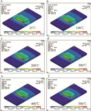
    Figure 1.  distribution of temperature field in cladding layer at different preheating temperatures

    图 1中可以看出,瞬态解最高温度随激光束的移动而移动。温度场温度最高值约为2300℃,位置稍滞后于光斑中心,温度高的熔池区域向温度低的基材区域递减,常温25℃的温度场瞬态解最高温度为2460℃,在预热温度为600℃时的温度场瞬态解最高温度为2543℃,温度场瞬态解的最高温度随基体预热温度的逐渐增加相应地增加,但增长幅度较小,说明影响温度场瞬态解最高温度主要为热源加载时间。在熔覆结束的同时,温度场瞬态解的最低温度由419℃增加到649℃,这说明瞬态解的最低温度受预热温度的影响较大,由不同预热温度的等温线可以看出,随着预热温度的逐渐提高,热影响区的温度逐渐提高,但温度场瞬态解的等温线较为分散,定性地说明了预热温度可以减小熔覆层和基体的温度梯度。

  • 得到熔覆完成时的温度场瞬态解,获得每一个节点的温度,导出熔覆层边缘与基材的节点温度,导出的熔覆层边缘与基材交界出的节点位置如图 2b图 2c所示。图中箭头所指的节点即为熔覆层和基材交界处,熔覆层的正视图如图 2a所示。

    Figure 2.  Temperature selection of the boundary node of the cladding layer and the base material

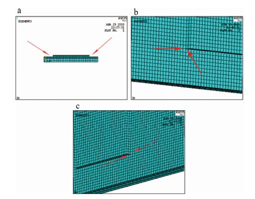
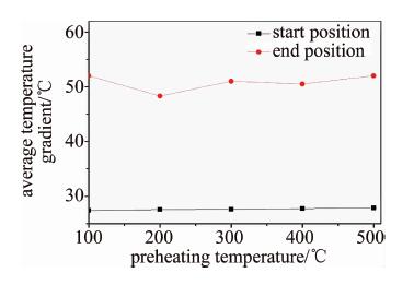
    根据熔覆层边界处提取的节点温度,以此计算熔覆层与基材边界上节点之间的平均温差,经数据的提取与处理,得到预热温度与平均温度梯度的变化, 如图 3所示。

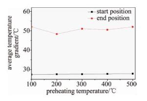
    Figure 3.  Relationship between preheating temperature and average temperature gradient

    图 3预热温度与平均温度梯度的变化趋势可以看出, 当预热温度逐渐提高时,熔覆层起始处的平均温度梯度波动较小,基本维持在27.5℃,这说明预热温度的提高对第1道熔覆层与基材的平均温度梯度影响较小。由图 3还可以看出, 熔覆层最后一道的平均温度梯度在预热温度为200℃时有所降低,这说明此时的温度梯度比预热温度为100℃和300℃时小,这就使得此时的熔覆层边界处与基体材料温度的温差较小,故选择预热温度为200℃,对于控制熔覆层与基材的裂纹有参考价值。

2.   温度梯度对熔覆层裂纹产生影响
  • 试验前材料处理:为了使45#钢表面平整无油污,试验前对基材表面进行精磨,使用无水乙醇清洗,在实验开始前对镍基熔覆粉末真空烘干除潮。表 1中为45#钢基材上的激光熔覆工艺参量。

    laser power/kW spot diameter/mm pulverized speed/(g·s-1) scanning speed/(mm·s-1) lap rate/% defocus/mm
    1.0 2 1.2 3 50 16

    Table 1.  Process parameters of laser cladding

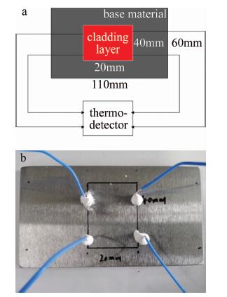
  • 图 4a为热电偶实验示意图,图 4b为贴在熔覆层起始和结束处边缘的热电偶。为了简化实验,在熔覆层边界第1道和最后一道的中部各粘接两个热电偶。

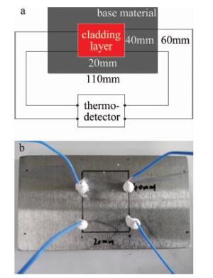
    Figure 4.  Connection of temperature measurement device

    根据实际情况, 通过对基材的熔覆实验可以得到熔覆层边缘的温度,由智能仪器接收数据并进行保存,导出数据对结果进行分析,热电偶温度实验结果如图 5所示。

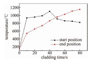
    Figure 5.  Trend of the first and last temperature during the cladding process

    根据图 3预热温度与平均温度梯度有限元软件仿真的结果,选择的预热温度为200℃的基材进行试验。由图 5可以看出,再将基材加热到200℃时,温度测试仪上并没有达到200℃,这是由于热电偶只能在理论上无限接近熔覆层,又由于热电偶与基材的粘接需要耐高温胶,这就使得热电偶获得的温度和实际有一定的误差,经实验测试获得的温度能反映激光熔覆进行时温度梯度的趋势就达到了试验的要求。根据图 5中的温度变化曲线可以看出,当熔覆层开始熔覆时第1道的温度急剧上升,且随着激光熔覆的进行热影响区的扩大,熔覆最后一道的温度也随之升高,在到达熔覆最后一道时温度达到最高,和实际激光熔覆试验的温度梯度的趋势是一致的,得到的结果可以作为激光熔覆实际加工生产中的依据。

  • 常温情况下与预热温度熔覆效果如图 6所示。

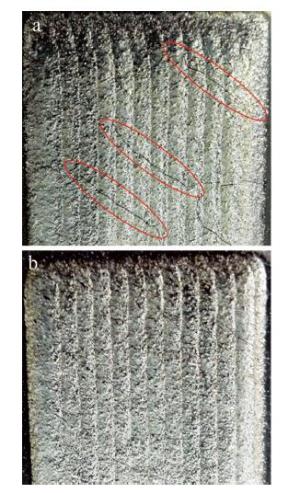
    Figure 6.  Macrograph of cladding layer

    通过常温情况下与预热温度实际的熔覆效果图可以看出, 图 6a中存在较多的且呈不规则分布的裂纹,在熔覆层的边界处存在细小的裂纹,这是由于在熔覆层中的熔池在凝固的过程中,熔池内部与部分熔化的基材之间存在较大的温度梯度,使得熔覆层在凝固的过程中易产生裂纹,这对于熔覆层的质量产生较大影响。由熔覆层宏观形貌图(见图 6b)可以看出,熔覆层表面无明显的裂纹且熔覆层较为平整,这是由于具有一定的预热温度,使得基体和熔覆层之间的温度梯度较小。对比图 6a图 6b可以看出, 在熔覆层与基体的交界处,没有预热的基材由于基材温度升高过快,导致氧化现象严重,对基材产生较大热影响且容易变形。这从实际试验中说明预热温度可以减少熔覆层裂纹的产生。

  • 熔覆层中部微观组织形貌图如图 7所示。

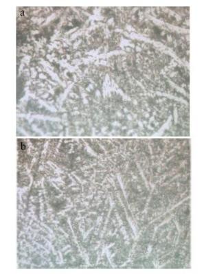
    Figure 7.  Microstructure and morphology of cladding layer

    图 7a图 7b为光学显微镜放大600倍时熔覆层中部的晶粒分布图。可以看出, 在两种常温和预热200℃温度的情况下,两种微观形貌图均未产生明显的裂纹,得到了较好的中部熔覆层。由图 7a可以看出, 晶粒粗大且生长相较于图 7b细小晶粒的规则分布,图 7a中的晶粒粗大,这是由于在熔池凝固的过程中,散热方向决定金属熔池晶粒生长,基材没有预热温度时,熔池散热呈分散状,最终表现为晶粒分布散乱。由于图 7b中的预热温度为200℃, 熔覆层温度梯度相较于常温基材的熔覆层较小,晶粒的生长受基材温度的影响较小,故晶粒排列较常温的(见图 7a)具有方向性且晶粒细小。

3.   结论
  • (1) 通过有温度场模拟与热电偶实验得出在基材为45#钢激光熔覆镍基粉末时,预热温度为200℃时, 激光熔覆层与基材的平均温度梯度较小,有利于裂纹的减少。

    (2) 随着预热温度在一定范围内提高逐渐升高,熔覆层边界与基材交界处的温度梯度逐渐降低,这就使得熔覆层与基材的之间因为温度梯度过大产生裂纹的情况减少。

    (3) 使用ANSYSY仿真软件建立熔覆温度场有限元模型,通过温度场模拟对比热电偶测温实验结果,这种模拟与实验的结合为实际加工生产提供了切实可行的参考依据。

Reference (18)

Catalog

    /

    DownLoad:  Full-Size Img  PowerPoint
    Return
    Return