Advanced Search

ISSN1001-3806 CN51-1125/TN Map

Volume 43 Issue 4
Jul.  2019
Article Contents
Turn off MathJax

Citation:

Calibration and design of long focal length measurement instruments based on Talbot-Moiré effect

  • Received Date: 2018-07-11
    Accepted Date: 2018-09-26
  • In order to meet the test and calibration requirements of 100m~3km extra-long focal length, a set of long focal length measurement instrument was designed based on Talbot-Moiré fringes. Aiming at the system parameters affecting the measurement uncertainty, different calibration methods were designed respectively. Experiments were carried out to verify the results. The results show that, after calibration, the measurement uncertainty is 6.4%. Measurement results of the long focal length measurement instrument after calibration, and knife-edge instrument meet the measurement uncertainty formula. The maximum comparison result is 0.64, less than 1. Uncertainty evaluation of the long focal length measurement instrument is reasonable. The research validates the feasibility of calibration methods for system parameters of a long focal length measurement instrument.
  • 加载中
  • [1]

    MESHCHERYAKOV V I, SINEL'NIKOV M I, FILIPPOV O K. Measuring the focal lengths of long-focus optical system[J]. Journal of Optical Technology, 1999, 66(5):458-459. doi: 10.1364/JOT.66.000458
    [2]

    DEBOO B, SASIAN J. Precision focal-length measurement technique with a relative Fresnel-zone hologram[J]. Applied Optics, 2003, 42(19):3903-3909. doi: 10.1364/AO.42.003903
    [3]

    ZHAO W Q, SUN R D, QIU L R, et al. Laser differential confocal radius measurement[J]. Optical Express, 2010, 18(3):2345-2360. doi: 10.1364/OE.18.002345
    [4]

    ZHAO W Q, SUN R D, QIU L R, et al. Laser differential confocal ultra-long focal length measurement[J]. Optical Express, 2009, 10(22):20051-20062.
    [5]

    ZHAO W Q, TAN J B, QIU L R. Bipolar absolute differential confocal approach to higher spatial resolution[J]. Optical Express, 2004, 12(21):5013-5021. doi: 10.1364/OPEX.12.005013
    [6]

    NAKANO Y, KAZUMI M. Measurements of phase objects using the Talbot effect and Moiré techniques[J]. Applied Optics, 1984, 24(14):2296-2299.
    [7]

    NAKANO Y, KAZUMI M. Talbot interferometry for measuring the focal length of a lens[J]. Applied Optics, 1985, 24(19):3162-3166. doi: 10.1364/AO.24.003162
    [8]

    CHEN H, HE Y, LI J X, et al. Measurement of long focal lengths with a double-grating interferometer[J]. Applied Optics, 2013, 52(27):6696-6702. doi: 10.1364/AO.52.006696
    [9]

    JIN X R, ZHANG J Ch, BAI J, et al. Calibration method for high-accuracy measurement of long focal length with Talbot interferometry[J]. Applied Optics, 2012, 51(13):2407-2413. doi: 10.1364/AO.51.002407
    [10]

    WANG M J, WU Zh G, XU D P, et al. Accurate and automatic re-cognition of Moiré fringe angle[J]. Chines Optics, 2011, 4(5):509-513(in Chinese).
    [11]

    CHEN H, ZHANG H, FAN H Y, et al. Measurement of laser wavefront curvature radius based on Talbot-Moiré fringe[J]. Laser Technology, 2018, 42(2): 156-160(in Chinese).
    [12]

    WU L L, WU G J, CANG Y P, et al. Image processing of Moiré fringes of measuring focal length of lens based on Talbot-Moiré[J]. Acta Photonica Sinica, 2010, 39(9): 1723-1727(in Chinese). doi: 10.3788/gzxb
    [13]

    WU L L, WANG X, CHEN J, et al. Limit precision analysis of focal length measurement of lens based on Talbot-Moiré[J]. Journal of Applied Optics, 2011, 32(4): 693-697(in Chinese).
    [14]

    WU L L, WU G J, CANG Y P, et al. Sub pixel calibration of mea-suring focal length of lens based on Talbot-Moiré[J]. Acta Photonica Sinica, 2010, 39(10): 1896-1900(in Chinese). doi: 10.3788/gzxb
    [15]

    LU H, CHEN H, HE Y, et al. Alignment method for measurement of long focal length based on Talbot-Moiré effect[J]. Infrared and Laser Engineering, 2013, 42(10):2836-2841(in Chinese).
    [16]

    ZHAO K, CHEN H X. Methods of measuring the long focal length of lens based on talbot effect and Moiré technique[J]. China Measurement Technology, 2004, 30(6):24-26(in Chinese).
    [17]

    LI X R. High precision subdivision of Moiré fringe[J]. Opto-Electronic Engineering, 2007, 34(11):74-77(in Chinese).
    [18]

    HOU Ch L, BAI J, HOU X Y, et al. The accurate measurement of angle based on Talbot effect of Ronchi grating[J]. Optical Instruments, 2004, 264(1):11-14(in Chinese).
  • 加载中
通讯作者: 陈斌, bchen63@163.com
  • 1. 

    沈阳化工大学材料科学与工程学院 沈阳 110142

  1. 本站搜索
  2. 百度学术搜索
  3. 万方数据库搜索
  4. CNKI搜索

Figures(8) / Tables(3)

Article views(4848) PDF downloads(21) Cited by()

Proportional views

Calibration and design of long focal length measurement instruments based on Talbot-Moiré effect

  • 1. Southwest Institute of Technical Physics, Chengdu 610041, China
  • 2. Military Represnetative Office of Army Airforce Stationed in Chengdu, Chengdu 610036, China

Abstract: In order to meet the test and calibration requirements of 100m~3km extra-long focal length, a set of long focal length measurement instrument was designed based on Talbot-Moiré fringes. Aiming at the system parameters affecting the measurement uncertainty, different calibration methods were designed respectively. Experiments were carried out to verify the results. The results show that, after calibration, the measurement uncertainty is 6.4%. Measurement results of the long focal length measurement instrument after calibration, and knife-edge instrument meet the measurement uncertainty formula. The maximum comparison result is 0.64, less than 1. Uncertainty evaluation of the long focal length measurement instrument is reasonable. The research validates the feasibility of calibration methods for system parameters of a long focal length measurement instrument.

引言
  • 随着长焦距光学系统在激光核聚变驱动器、天文光学系统、空间遥感相机、高能激光器等领域的广泛应用,对长焦距参量的精确测量成为光学测量领域的研究热点。目前已提出了多种长焦距参量的测量方法。MESHCHERYAKOV等人[1]提出利用楔角很小的高精度光楔测量长焦距参量,实验结果表明, 在测量25m长焦距时精度可达0.1%;DEBOO等人[2]利用菲涅耳全息片和移相干涉仪测量长焦距,实验表明,测量结果精度可优于0.01%;ZHAO等人[3-5]提出利用差动共焦技术测量焦距,在测量5m以内焦距时精度较高;NAKANO等人[6-7]最早提出基于Ronchi光栅的Talbot-Moiré条纹技术测长焦距方法,测量精度一般能达到0.02%。基于Talbot-Moiré条纹技术法具有结构简单、精度高等特点,尤其适用于长焦距的测量,国内外学者对此测量技术进行了深入的研究[8-18]

    作者针对测量口径为200mm、测量范围覆盖100m~3km、超长焦距参量的测试校准需求,设计了基于Talbot-Moiré条纹技术的长焦测焦仪,并对仪器参量进行了校准,对测量不确定度进行评估及实验验证。

1.   基本原理
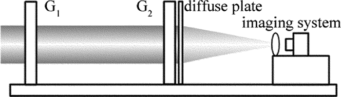
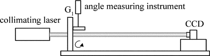
  • 基于Talbot-Moiré条纹技术测量长焦距参量的结构布局如图 1所示。主要由双光栅、光屏、条纹成像系统、计算软件等组成。其测量原理为:Ronchi光栅G1和G2平行放置且两光栅栅线之间存在一个小角度,待测球面波经光栅G1后,在右侧某一确定泰伯距离处将存在一个和原光栅栅线方向相同的泰伯像,泰伯像与光栅G2叠合后在光屏上形成莫尔条纹,不同焦距对应莫尔条纹不同倾角,通过条纹角度求解算法精确求出莫尔条纹倾角,最后解算出待测焦距值。根据理论推导,待测焦距计算公式为:

    Figure 1.  Optical configuration for focal length measurement based on Talbot-Moiré effect

    式中, f为待测焦距;d为光栅间距;θ为两光栅栅线夹角;φ为莫尔条纹倾角;p1, p2分别为光栅G1, G2的光栅周期。

2.   系统设计
  • 由测量原理可知,系统的设计主要包括光栅间距、光栅夹角、光栅周期的设计,下面将依据测量范围、量值灵敏度、系统复杂度等优化设计各项系统参量。

    根据(1)式,当两光栅周期相同,按不确定度传播率计算,光栅间距、光栅夹角、莫尔条纹倾角的不确定度与焦距结果的标准测量不确定度关系为:

    式中,u(f)为焦距测量结果的标准测量不确定度; u(d), u(θ), u(φ)分别代表光栅间距、光栅夹角、莫尔条纹倾角的标准测量不确定度; c1~c3为不确定度传播系数。对测量不确定度合成公式分析可知,焦距结果相对标准不确定度随待测焦距的增大而增大,因此主要分析3km处的相对测量不确定度,分析系统参量选取对焦距测量不确定度的影响关系,计算时选取光栅间距、光栅夹角、莫尔条纹倾角的测量不确定度分别为0.05mm, 20″,20″。

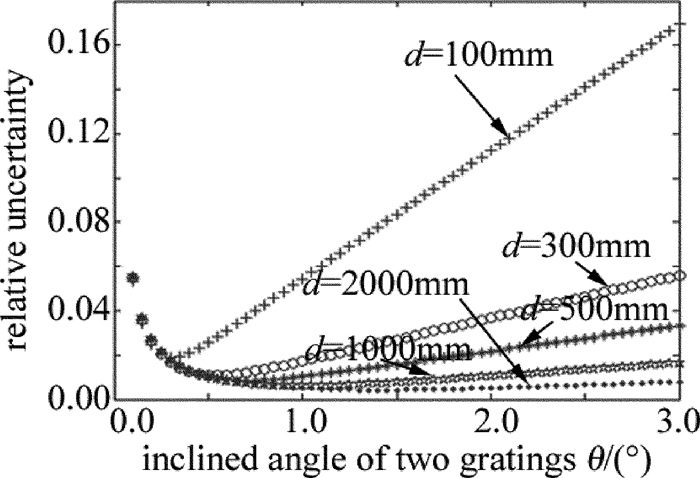
  • 由(2)式~(5)式计算不同光栅间距条件下焦距测量不确定度随光栅夹角的变化关系曲线,如图 2所示。测量不确定度随光栅间距的增大而减小,综合考虑测量不确定度要求及系统紧凑性,选择光栅间距为500mm。

    Figure 2.  Relative measurement uncertainty vs. the inclined angle of two gratings

  • 图 2可以看出,同一光栅间距下,相对标准测量不确定度存在极小值,因此选择极小值对应的光栅夹角作为设计值。经计算,光栅间距为500mm时,测量不确定度极小值对应的光栅夹角为0.7°。

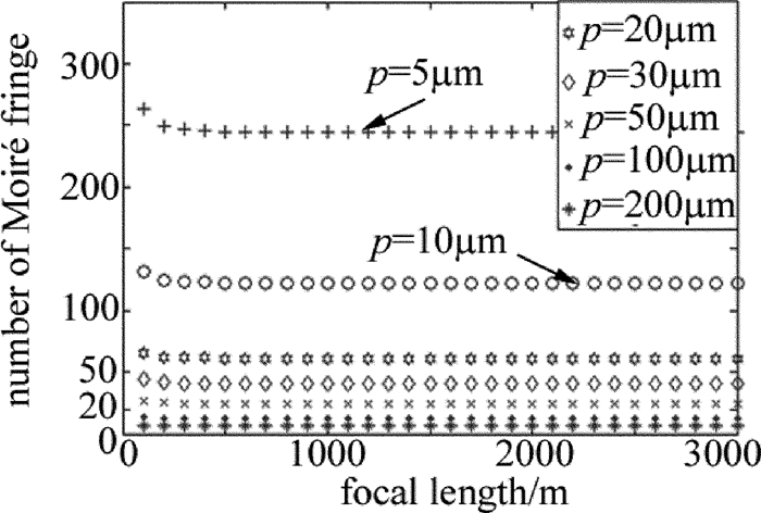
  • 光栅周期影响产生莫尔条纹宽度,进而影响通光口径内条纹数,目前主流采用的傅里叶频谱变换法计算条纹倾角,通常要求待处理条纹数满足20≤N≤200。图 3为选取不同光栅周期时的干涉条纹数量N与待测焦距间关系。由图可知,光栅周期p为10μm~50μm时满足要求,同时考虑CCD相机直接记录光栅泰伯像及精确测量光栅栅线方向角要求,选择光栅周期为20μm。

    Figure 3.  Relationship between the number of Moiré fringes and focal length under different grating periods

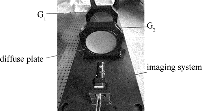
    依据设计结果,所研制的测焦仪器样机如图 4所示。系统有效通光口径为200mm,光栅周期为20μm,双光栅夹角为0.7°,双光栅间距为500mm。

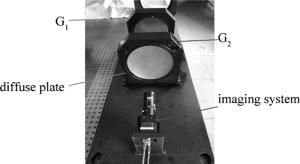
    Figure 4.  Photograph of testing system

3.   系统参量的校准及测量不确定评定
  • 对系统参量的校准主要包括光栅间距、光栅夹角、莫尔条纹倾角结果的校准,下面将分别介绍校准方法。

  • 光栅间距可以由精密测长仪器测量得到,测量不确定度主要来源为测长仪器的测量不确定度,可评估为0.05mm。

  • 光栅夹角的校准原理示意图如图 5所示。用CCD直接采集光栅G1的泰伯像,计算出光栅G1栅线的方向角,如图 5a所示;安装光栅G2,通过两块平行反射镜使准直光垂直照射G2,用CCD采集光栅G2的泰伯像,测量光栅G2栅线方向角,如图 5b所示;光栅G2栅线方向角与光栅G1栅线方向角之差即为光栅夹角的校准值。

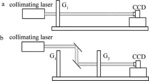
    Figure 5.  Calibration principle for the inclined angle of two gratings

    由校准原理可知,光栅夹角校准不确定度来源于CCD测量光栅栅线方向角的测量不确定度,评定光栅夹角结果测量不确定度的实验装置图如图 6所示。CCD固定,精密旋转光栅,CCD通过采集光栅泰伯像测量出光栅栅线方向角的变化量,将测量结果与测角装置测量结果进行比对完成光栅夹角测量不确定度的评定,测角装置测量不确定度小于1″,引入测量不确定度可忽略。实验结果如表 1所示。θ0为测角装置测量结果,θ1为CCD测量光栅栅线方向角变化结果,由结果可知光栅夹角测量不确定度为8″。

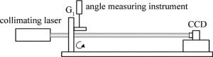
    Figure 6.  Scheatic of the experimental arrangement for evaluating uncertainty of the inclined angle of two gratings

    serial number θ0/(°) θ1/(°) (θ0-θ1)/(″)
    1 0.69999 0.7002 -0.76
    2 0.70005 0.6988 4.50
    3 0.70009 0.6994 2.48
    4 0.69998 0.6990 3.53
    5 0.69989 0.6993 2.12
    6 0.70003 0.7000 0.11
    7 0.69995 0.6979 7.38
    8 0.69999 0.6996 1.40
    9 0.70004 0.7004 -1.30
    10 0.70079 0.6993 5.36
    11 0.70094 0.7004 1.94
    12 0.70020 0.6997 1.80

    Table 1.  Experimental data for calibration of measuring the inclined angle of two gratings

  • 莫尔条纹倾角结果校准原理图如图 7所示。光栅、光屏、成像镜头等元件装调完成后固定,CCD相机采集莫尔条纹,单独精密旋转CCD相机,CCD上莫尔条纹倾角将发生变化,通过比对莫尔条纹倾角测量结果与测角装置测量结果, 完成对莫尔条纹倾角结果的校准。

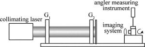
    Figure 7.  Calibration principle for Moiré fringe angle

    校准实验结果如表 2所示。表中α0为测角装置测量结果,α1为CCD测量莫尔条纹倾角变化结果。由数据可知, 莫尔条纹倾角结果测量不确定度为12″,考虑到测量坐标系的y轴是以G1栅线方向建立,莫尔条纹倾角结果还将包含光栅栅线方向角测量不确定度,两者合成结果为15″。

    serial number α0/(°) α1/(°) (α0-α1)/(″)
    1 1.05202 1.0493 9.79
    2 2.05154 2.0514 0.50
    3 3.05178 3.0498 7.13
    4 4.04212 4.0447 -9.29
    5 5.05064 5.0479 9.86
    6 6.04253 6.0395 10.91
    7 7.05006 7.0505 -1.58
    8 8.05094 8.0527 -6.34
    9 9.05202 9.0507 4.75
    10 10.05183 10.0497 7.67
    11 11.05151 11.0504 4.00
    12 12.05131 12.0494 6.88
    13 13.05148 13.0516 -0.43
    14 14.0516 14.0543 -9.72
    15 15.05137 15.0523 -3.35
    16 16.0514 16.0487 9.72
    17 17.05148 17.0508 2.45
    18 18.05136 18.0484 10.66
    19 19.05183 19.0518 0.11
    20 20.05142 20.0509 1.87
    21 21.05158 21.0549 -11.95
    22 22.05155 22.0537 -7.74
    23 23.05202 23.0519 0.43
    24 24.05147 24.0541 -9.47
    25 25.05186 25.0495 8.50
    26 26.05163 26.0509 2.63
    27 27.05168 27.0545 -10.15
    28 28.05167 28.0545 -10.19
    29 29.05203 29.0534 -4.93
    30 30.05196 30.0528 -3.02
    31 31.05176 31.0508 3.46
    32 32.05177 32.0548 -10.91
    33 33.05157 33.0491 8.89

    Table 2.  Experimental data for calibration of measuring the angle of Moiré fringes

4.   比对实验验证
  • 依据长焦测焦仪系统参量校准结果及测量不确定度,对设计长焦测焦仪测量3km焦距测量不确定度进行评定。

    (1) 光栅间距的不确定度给焦距的不确定度u1。光栅间距为500mm,测量不确定度为0.05mm,按不确定度传感公式,引入的测量不确定度为:u1=c1×0.05=0.3m。

    (2) 光栅栅线夹角的不确定度给焦距的不确定度u2。光栅夹角为0.7°,测量不确定度为8″,按不确定度传感公式,引入的测量不确定度为:u2=c2×8=5.3m。

    (3) 莫尔条纹倾角的不确定度给焦距的不确定度u3。莫尔条纹倾角测量不确定度为15″,按不确定度传感公式,引入的测量不确定度为:u3=c3×15=16.0m。

    (4) 光栅面形畸变引入的测量不确定度u4。光栅面形要求精确控制并通过干涉仪测量,面形均方根值小于λ/50,面形产生的焦距值大于100km,由此引入的不确定度可评估为:u4=87.4m。

    (5) 测量重复性引入的测量不确定度u5。测量3km焦距值,重复测量12次,由贝塞尔公式可求得重复性引入的测量不确定度为:u5=25.4m。

    各不确定度分量彼此无关,故合成标准不确定度为$u_{\mathrm{c}}=\sqrt{{u_{1}}^{2}+{u_{2}}^{2}+{u_{3}}^{2}+{u_{4}}^{2}+{u_{5}}^{2}}=92.6 \mathrm{m}$。

    扩展不确定度按下式计算:U=kuc=0.19km。其中, U为扩展不确定度;k为包含因子,取k=2;uc为合成不确定度。

    带入数据,相对扩展不确定度为:Ur=6.4%。

    用同样的方法,可评定出仪器100m~3km测量范围内测量不确定度,测量不确定度评定结果如图 8所示。

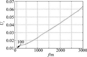
    Figure 8.  Evaluation result of measurement uncertainty

    为了验证评定测量不确定度的合理性,利用可调焦望远系统产生不同后焦距值,用长焦测焦仪测量望远系统出口焦距值,用刀口仪确定焦点位置并用测距机精确测量焦距值。考虑到刀口仪寻找焦点时,测量不确定度随焦距的增长而快速增加,另外激光长距离传输受空气扰动严重,因此在实验室光学通道完成了600m内测量结果的比对验证,刀口仪法测量不确定度通过多点测量焦深给出。实验结果如表 3所示,所有结果都满足比对公式:

    results of designed system results of knife-edge test system En
    Y1/m U1/m Y2/m U2/m
    99.3 1.2 99.1 0.5 0.15
    199.5 2.5 200.9 0.9 0.53
    291.7 4.0 288.6 3.1 0.61
    437.8 6.4 436.0 8.0 0.18
    564.2 9.1 570.0 9.0 0.45

    Table 3.  Results of comparative tests

    式中, Y1为焦距, 是长焦测焦仪测量结果;Y2是测距机测量结果;U1为长焦测焦仪扩展不确定度;U2为刀口仪法扩展不确定度。

5.   结论
  • 从测量公式(1)式及不确定度传播公式(2)式出发,优化设计了测焦装置的系统参量,对系统参量分别设计了校准方法并对校准结果测量不确定度进行了评定,校准结果最终溯源到国家长度、角度基准。为了验证校准结果的正确性,利用长距离光学通道完成了比对验证实验,从实验结果可看到,比对结果最大为0.61 < 1,满足比对公式,验证了设计测量系统测量不确定度优于6.4%,校准技术可广泛用于基于Talbot-Moiré条纹技术长焦测焦仪的校准工作。

Reference (18)

Catalog

    /

    DownLoad:  Full-Size Img  PowerPoint
    Return
    Return