 网站地图
网站地图


-
光纤布喇格光栅外腔半导体激光器(fiber Bragg grating external cavity laser diode,FBG-ECLD)有着窄线宽、低噪声、体积小、频率稳定、温度稳定性好、波长调谐方便、调制速度快等诸多优点[1],被广泛应用于密集波分复用(dense wavelength division multiplexing,DWDM)系统、谐振式光学陀螺[2]、空气痕量检测、高分辨率光谱测量、光电子检测、波长变换[3]等,因而备受国内外研究人员的关注[4-9]。
对FBG-ECLD的研究,现已取得了一定的成果,其理论模型主要为等效腔模型,在建模近似过程中,主要应用耦合腔近似或三腔镜近似。本文中对两种理论模型进行了比较分析,选出了最优模型,并利用最优模型进行了阈值增益的简单计算。
-
利用耦合模理论可以得到均匀余弦无啁啾单模Bragg光栅沿轴向(z向)的折射率分布为:
$ {\rm{ \mathsf{ δ} }}{n_{{\rm{eff}}}} = \overline {{\rm{ \mathsf{ δ} }}{n_{{\rm{eff}}}}} \left[ {1 + m\cos \left( {2{\rm{ \mathsf{ π} }}z/\mathit{\Lambda }} \right)} \right] $
(1) 式中,$\overline {{\rm{ \mathsf{ δ} }}{\mathit{n}_{{\rm{eff}}}}} $为纤芯折射率的平均变化量,m为条纹可见度,Λ为光栅周期。
光栅反射率系数为[10]:
$ \begin{array}{*{20}{c}} {{r_{\rm{g}}} = - \kappa {{\sinh }^2}\left( {\sqrt {{\kappa ^2} - \sigma _{\rm{c}}^2} {l_{\rm{g}}}} \right)/\left[ {{\sigma _{\rm{c}}}\sinh \left( {\sqrt {{\kappa ^2} - {\sigma _{\rm{c}}}^2} {l_{\rm{g}}}} \right) + } \right.}\\ {\left. {{\rm{i}}\sqrt {{\kappa ^2} - {\sigma _{\rm{c}}}^2} \cosh \left( {\sqrt {{\kappa ^2} - {\sigma _{\rm{c}}}^2} {l_{\rm{g}}}} \right)} \right]} \end{array} $
(2) 式中,σc是总直流自耦合系数,σc=δ+σ,δ=2πneff×(1/λ-1/λd)为失谐度,与z无关;λd为设计波长(Bragg波长), λd=2neffΛ,neff为光纤纤芯原折射率; σ=(2π/λ)$\overline {{\rm{ \mathsf{ δ} }}{\mathit{n}_{{\rm{eff}}}}} $为功率损耗系数;κ为交流耦合系数, κ=πm$\overline {{\rm{ \mathsf{ δ} }}{\mathit{n}_{{\rm{eff}}}}} $/λ;lg为光栅的长度。
反射率R=|rg|2为:
$ R = \frac{{{\kappa ^2}{{\sinh }^2}\left( {\sqrt {{\kappa ^2} - {\sigma _{\rm{c}}}^2} {l_{\rm{g}}}} \right)}}{{{\kappa ^2}{{\cosh }^2}\left( {\sqrt {{\kappa ^2} - {\sigma _{\rm{c}}}^2} {l_{\rm{g}}}} \right) - {\sigma _{\rm{c}}}^2}} $
(3) -
由于未切趾光纤Bragg光栅两端面与光纤折射率突变,形成F-P腔,使得反射率有较大旁瓣,边模抑制比较低。同时较多的旁瓣反射过多无用波长光波,使得器件性能降低。切趾技术可以避免折射率突变,抑制旁瓣。现行比较常见的切趾技术有Gaussian, Hamming, Blackman, tanh, sinc等类型切趾。本文中以Gaussian型切趾为例,进行简要介绍。
Gaussian切趾函数为:
$ \overline {{\rm{ \mathsf{ δ} }}{n_{{\rm{eff}}}}} \left( z \right) = \overline {{\rm{ \mathsf{ δ} }}{n_{{\rm{eff}}}}} \exp \left[ { - G{{\left( {z/{L_{{\rm{FWHM}}}}} \right)}^2}} \right] $
(4) 式中,G为切趾深度; LFWHM为光栅折射率分布剖面的半峰全宽, 本文中取LFWHM=lg[11]。进行切趾后,(1)式变为:
$ {\rm{ \mathsf{ δ} }}{n_{{\rm{eff}}}}\left( z \right) = \overline {{\rm{ \mathsf{ δ} }}{n_{{\rm{eff}}}}} \left( z \right)\left[ {1 + m\cos \left( {2{\rm{ \mathsf{ π} }}z/\mathit{\Lambda }} \right)} \right] $
(5) 切趾前后的光栅折射率分布示意图分别如图 1a和图 1b所示。
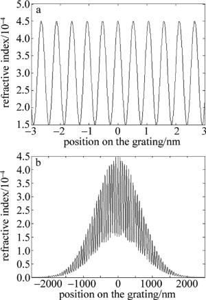
Figure 1. Refractive index profile of fiber Bragg grating before and after apodization
分析切趾光栅的反射率常采用传输矩阵法。将FBG均分为M段,每段可看成是均匀FBG,每段FBG的长度为Δz,则第i段的传输矩阵为:
$ \begin{array}{*{20}{c}} {{\mathit{\boldsymbol{F}}_{{\rm{B}},i}} = }\\ {\left[ {\begin{array}{*{20}{c}} {\cosh \left( {\gamma \Delta z} \right) - {\rm{i}}\frac{{{\sigma _{\rm{c}}}}}{\gamma }\sinh \left( {\gamma \Delta z} \right)}&{ - {\rm{i}}\frac{\kappa }{\gamma }\sinh \left( {\gamma \Delta z} \right)}\\ {{\rm{i}}\frac{\kappa }{\gamma }\sinh \left( {\gamma \Delta z} \right)}&{\cosh \left( {\gamma \Delta z} \right) + {\rm{i}}\frac{{{\sigma _{\rm{c}}}}}{\gamma }\sinh \left( {\gamma \Delta z} \right)} \end{array}} \right]} \end{array} $
(6) 式中,$ \gamma = \sqrt {{\kappa ^2} - {\sigma _{\rm{c}}}^2} $。
整个光栅的矩阵表示为:
$ \left[ {\begin{array}{*{20}{c}} {{R_M}}\\ {{S_M}} \end{array}} \right] = \mathit{\boldsymbol{F}}\left[ {\begin{array}{*{20}{c}} {{R_0}}\\ {{S_0}} \end{array}} \right] $
(7) 式中,F=FM·FM-1…F1; Rj, Sj分别为光经过j段光栅后的反射和入射振幅。在理想初始条件下,R0=1,S0=0。
根据(4)式~(7)式,通过MATLAB软件计算,可得到切趾与未切趾光栅的反射率以及不同切趾深度下的光栅反射率图形,如图 2、图 3所示。
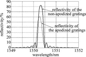
Figure 2. Reflectivity of apodized grating and non-apodized grating
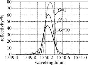
Figure 3. Reflectivity of gratings with different apodization
-
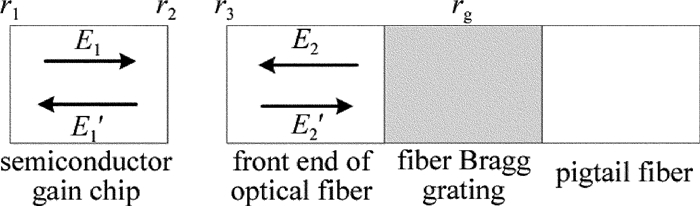
图 4是典型的FBG-ECLD的结构示意图。l1是增益芯片的增益区的长度,l2是增益芯片前端到光栅中点的长度,r1和r2分别为半导体芯片后、前端反射率系数。实际应用中,为了得到较大的输出功率和良好的激光特性,常在增益芯片前端镀增透膜(r2 < 0.01)。
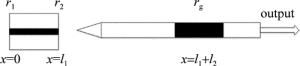
Figure 4. Schematic diagram of FBG-ECLD
等效腔理论模型忽略了光纤端面细节,把Bragg光栅等效成一个普通外腔镜,利用三腔镜模型[12-13],将增益芯片前端面(靠近耦合光纤的端面)、光纤、光栅等效成一个反射面(等效反射面的反射率称为等效反射率Reff),这样外腔激光器就可以等效成一个普通半导体激光器,从而可利用激光谐振的相位和增益条件[14]或者射线法[15]分别对FBG-ECLD进行离散波长或连续波长分析。图 5是三腔镜近似模型的示意图,ε1和ε0分别为增益芯片和空气的介电常数,r3′为光栅等效成反射镜面后的反射率系数。图 6是等效腔模型示意图。
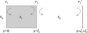
Figure 5. 1-D model of FBG-ECLD in three cavity mirrors approximation
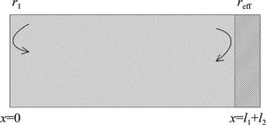
Figure 6. Equivalent cavity model of FBG-ECLD
可以通过计算光在外腔中多次反射的时延特性[16],或利用电磁场理论,考虑电场在复合腔中的边界条件,得出等效反射率系数reff[12-13]:
$ {r_{{\text{eff}}}} = \left( {{r_2} + {r_3}^\prime {{\text{e}}^{ - {\text{i}}{\varphi _0}}}} \right)/\left( {1 + {r_2}{r_3}^\prime {{\text{e}}^{ - {\text{i}}{\varphi _0}}}} \right) $
(8) 式中,φ0是外腔引入的相位变化。
在此基础上,考虑到增益芯片和光纤存在一定的耦合效率,引入耦合效率η,并简单唯象地把光纤耦合效率增加到r3′中,得到修正了的等效反射率系数公式为[7]:
$ {r_{{\rm{eff}}}} = \left( {{r_2} + \eta \left| {{r_{\rm{g}}}} \right|{{\rm{e}}^{ - {\rm{i}}{\varphi _0}}}} \right)/\left( {1 + {r_2}\eta \left| {{r_{\rm{g}}}} \right|{{\rm{e}}^{ - {\rm{i}}{\varphi _0}}}} \right) $
(9) 式中,φ0=4πl2/λ。
在以上分析过程中,把|rg|近似处理为镜面反射系数,并忽略了其复数特性。而从第1.1节中的分析可知|rg|有一个反射率分布[17],且其峰值会与Bragg波长有一个红移。基于这个物理事实,在分析等效反射率系数的时候,应将|rg|的分布及中心波长偏移特性考虑在内。
-
耦合腔理论模型同样把光纤Bragg光栅近似为普通反射镜,并将耦合腔半导体激光器的[18]的分析方法应用于FBG-ECLD上,把增益芯片和光纤的耦合作用通过散射矩阵表示[19]:
$ \left[ {\begin{array}{*{20}{c}} {{E_1}^\prime } \\ {{E_2}^\prime } \end{array}} \right] = \left[ {\begin{array}{*{20}{c}} {{S_{11}}}&{{S_{12}}} \\ {{S_{21}}}&{{S_{22}}} \end{array}} \right]\left[ {\begin{array}{*{20}{c}} {{E_1}} \\ {{E_2}} \end{array}} \right] $
(10) 图 7为耦合腔模型示意图。对于空气间隙而言,E1, E2分别为来自增益芯片和光纤端的入射电磁场,相应地,E1′, E2′为反射电磁场,r3为光纤端面的反射率系数。由矩阵元Sij构成散射矩阵。当考虑光在空气间隙中多次往复传播后,得到各个矩阵元为[19]:
$ \left\{ {\begin{array}{*{20}{l}} {{S_{11}} = {r_1} - \frac{{{r_3}\left( {1 - {r_2}^2} \right){t_{\text{a}}}{\eta _1}{\eta _2}}}{{1 - {r_2}{r_3}{t_{\text{a}}}{\eta _1}{\eta _2}}}} \\ {{S_{22}} = {r_2} - \frac{{{r_2}\left( {1 - {r_3}^2} \right){t_{\text{a}}}{\eta _1}{\eta _2}}}{{1 - {r_2}{r_3}{t_{\text{a}}}{\eta _1}{\eta _2}}}} \\ {{S_{12}} = \frac{{{{\left[ {{t_{\text{a}}}\left( {1 - {r_2}^2} \right)\left( {1 - {r_3}^2} \right){\eta _2}} \right]}^{1/2}}}}{{1 - {r_2}{r_3}{t_{\text{a}}}{\eta _1}{\eta _2}}}} \\ {{S_{12}} = \frac{{{{\left[ {{t_{\text{a}}}\left( {1 - {r_2}^2} \right)\left( {1 - {r_3}^2} \right){\eta _1}} \right]}^{1/2}}}}{{1 - {r_2}{r_3}{t_{\text{a}}}{\eta _1}{\eta _2}}}} \end{array}} \right. $
(11) 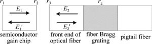
Figure 7. Coupled cavity model
式中,ta=exp(i2βala)=exp(i2k0la)exp(-αala)和tf=exp(i2βflf)分别为光在空气间隙和光纤中往返渡越一周后的变化因子,la为空气间隙的长度(即工作距离),lf为光纤端面到光栅的距离。βa和βf分别为光在空气和光纤中的传播常数。η1为增益芯片到光纤的耦合系数,η2为光纤到增益芯片的耦合系数,为了简单起见,本文中下述讨论建立在η1=η2的基础上。并且:k0=2π/λ,αa=2k0ka,ka为空气消光系数,βf=nfk0, nf是光纤纤芯折射率。
同样应用等效腔理论,得到等效反射率系数为:
$ {r_{{\rm{eff}}}} = {S_{11}} + {r_{\rm{g}}}{t_{\rm{f}}}{S_{12}}{S_{21}}/\left( {1 - {r_{\rm{g}}}{t_{\rm{f}}}{S_{22}}} \right) $
(12) -
当激光在谐振腔内往返一周后,若损耗恰好等于增益,则称此时的条件为阈值条件。在本征激光器内,阈值增益为:
$ {g_{{\rm{th}},0}} = \alpha + {l_1}^{ - 1}\ln \left( {{r_1}^{ - 1}{r_2}^{ - 1}} \right) $
(13) 式中, α为腔损耗,主要由自由载流子吸收和存在的各种散射引起。
外腔激光器中,阈值增益为:
$ {g_{{\rm{th}}}} = \alpha + {l_1}^{ - 1}\ln \left( {{r_1}^{ - 1}{{\left| {{r_{{\rm{eff}}}}} \right|}^{ - 1}}} \right) $
(14) 式中, |reff|为reff的模。
-
利用三腔镜模型和耦合腔模型分别计算FBG-ECL的等效反射率,相对于以往计算,本文中充分考虑了光栅反射率分布、中心波长偏移等因素带来的影响。计算时使用的数据在表 1中列出。
Table 1. Calculation date
parameter value original refractive index of optical fiber core neff 1.46 fringe visibility m 0.5 length of the fiber lg 5mm average refractive index change $\overline {{\rm{ \mathsf{ δ} }}{\mathit{n}_{{\rm{eff}}}}} $ 0.0003 length of the external cavity l2 10mm reflectivity coefficient of the gain chip's back-end r1 $\sqrt {0.9} $ reflectivity coefficient of the gain chip's front-end r2 0.01 reflectivity of fiber facet r3 0.05 coupling coefficient η 70% refractive index of the semiconductor chip n1 3.4 length of the active region of semiconductor l1 300μm cavity loss α 20cm-1 extinction coefficient of air ka 0.01 apodization degree G 5 -
图 8~图 10分别为切趾和未切趾情况下的等效反射率Reff=|reff|2的分布图形。

Figure 8. Equivalent reflectivity of two models when using non-apodized grating
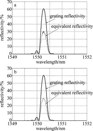
Figure 9. Equivalent reflectivity of two models when G=5

Figure 10. Equivalent reflectivity of two models when G=200
图 8a、图 9a、图 10a为使用三腔镜近似的情况,图 8b、图 9b、图 10b为使用耦合腔近似的情况。可以看出,在未切趾的情况下,两种近似方法所得的等效反射率近似相同,但需要注意的是,耦合腔近似下,在峰值反射率周围,出现小的波动。从整体图形上看,耦合腔近似也不如三腔镜近似得到等效反射率与光栅反射率匹配。唯象而言,无论哪种近似,增益芯片前端面(未镀增透膜)、空气间隙、光纤透镜均无波长选择性,三者构成的整体对不同波长光波的反射率应一致。事实上,在以上分析过程中,对于镀膜器件,仅考虑了膜层对反射率的单值影响,并未关注其波长分布情况。所以,整个FBG-ECLD器件的波长选择无源器件中,只需要分析光纤Bragg光栅的波长选择性(即反射率分布)。
在光纤Bragg光栅切趾后,旁瓣得到有效抑制,但是随着切趾深度G的增加,可以看出耦合腔近似进一步恶化,反射率抖动加剧。为了突出问题,将G取值为200,可以看到等效反射率波动较大,在光栅反射率的边缘位置,耦合腔近似情况下的等效反射率已经大于光栅反射率,与实际情况严重背离,说明这种近似方法已经不再适用。而利用三腔镜近似的模拟图像,仍可以得到较为符合实际的图形。出现这种情况的原因可能是光栅的反射率分布对耦合腔近似的影响较大。或者说光栅切趾后缓变的折射率相对于未切趾光栅的突变折射率而言,对耦合腔近似模型的影响更大。
-
针对2.1节中的分析,采用三腔镜模型对FBG-ECLD的阈值进行分析。
图 11a和图 11b分别是采用未切趾和高斯切趾光栅时的等效透射率与增益阈值关系图。光栅经过切趾后,单边(长波长)边模抑制比提高,但是短波长方向仍存在一定程度的旁瓣,其主要原因是使用Gaussian切趾后,对长波长方向的一级旁瓣抑制较好,对短波长方向的一级旁瓣抑制较差。其改进方法可以参考文献[20]中给出的二次曝光法。另外,可以看出无论切趾与否,阈值增益的带宽都有一定程度的增加,阈值增益的带宽随着FBG带宽的增大而增大,所以,减小阈值增益带宽的最直接最有效的办法就是减小FBG的带宽。光栅带宽过宽,使波长选择性恶化,其等效结果就与普通腔镜类似。对于要求单模性极好的FBG-ECLD而言,这是需要避免的。当FBG透射谱带宽为0.4nm时,外腔半导体激光器表现出了良好的单模特性[21]。从现在常用的相位掩模板的制作切趾光栅的方法来看,切趾光栅边模抑制比的提高是以反射率-3dB带宽为代价的[22],这一点从图 3也可以看出。所以,在设计应用于FBG-ECLD的Bragg光栅时,应综合考虑增益带宽和边模抑制比,选择适当的光栅参量进行设计制作。
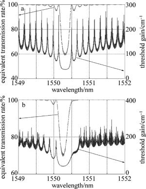
Figure 11. Equivalent transmission and gain threshold when using the apodized and non-apodized gratings
-
分别分析了利用基于三腔镜近似和耦合腔近似的FBG-ECLD等效腔模型。在模拟计算中可以看出,对于未切趾光纤光栅,两种近似情况下的模型基本一致,但对于切趾光栅,且在切趾深度较大的情况下耦合腔近似会出现较大误差,不再适用。而为了提高FBG-ECLD整体的边模抑制比,一般需要选用旁瓣抑制效果好的切趾Bragg光栅,在这种情况下使用三腔镜近似的等效腔模型更加符合实际情况。在三腔镜近似下,分析了FBG-ECLD的阈值增益特性,并分析了光栅特性对增益的影响,对实际设计制作光纤Bragg光栅,有一定的指导意义。
光纤光栅外腔半导体激光器理论模型分析与选取
Selection and analysis of theoretical model of fiber Bragg grating external cavity laser diode
-
摘要: 为了讨论三腔镜近似或耦合腔近似两种等效腔模型对计算光纤光栅外腔半导体激光器等效反射率等参量的近似程度,挑选出最优的理论模型,采用数值计算的方法进行模拟仿真,得到了两种模型在采用切趾光纤Bragg光栅和非切趾光纤Bragg光栅情况下的阈值增益等特性曲线。结果表明,在采用切趾光纤Bragg光栅,特别是切趾深度较大的情况下,采用三腔镜近似模型更加符合实际情况。此研究结果对分析和设计单纵模光纤光栅外腔半导体激光器具有一定的参考价值。Abstract: In order to discuss approximation degree of calculating equivalent reflectivity and other parameters of the fiber Bragg grating external cavity laser diode by using two equivalent cavity models of the three cavity mirrors approximation or the coupled cavity approximation and choose the best one, the threshold gain characteristic curves of two approximation models by using apodized fiber Bragg grating and normal fiber Bragg grating were gotten after numerical caculation and simulation. Numerical analysis results show that three cavity mirrors approximate model is more in line with the actual situation when using the apodized fiber Bragg grating. This conclusion has the reference in analysing and designing single longitudinal mode fiber grating external cavity semiconductor laser.
-
Figure 1. Refractive index profile of fiber Bragg grating before and after apodization
Figure 8. Equivalent reflectivity of two models when using non-apodized grating
a—the three cavity mirrors model when using fiber Bragg gratings before apodized b—the coupled cavity model when using fiber Bragg gratings before apodized
Figure 9. Equivalent reflectivity of two models when G=5
a—the three cavity mirrors model b—the coupled cavity model
Figure 10. Equivalent reflectivity of two models when G=200
a—the three cavity mirrors model b—the coupled cavity model
Figure 11. Equivalent transmission and gain threshold when using the apodized and non-apodized gratings
a—the equivalent transmission and gain threshold when using fiber Bragg gratings before apodized b—the equivalent transmission and gain threshold when using Gaussian-apodized fiber Bragg gratings
Table 1. Calculation date
parameter value original refractive index of optical fiber core neff 1.46 fringe visibility m 0.5 length of the fiber lg 5mm average refractive index change $\overline {{\rm{ \mathsf{ δ} }}{\mathit{n}_{{\rm{eff}}}}} $ 0.0003 length of the external cavity l2 10mm reflectivity coefficient of the gain chip's back-end r1 $\sqrt {0.9} $ reflectivity coefficient of the gain chip's front-end r2 0.01 reflectivity of fiber facet r3 0.05 coupling coefficient η 70% refractive index of the semiconductor chip n1 3.4 length of the active region of semiconductor l1 300μm cavity loss α 20cm-1 extinction coefficient of air ka 0.01 apodization degree G 5  下载: 导出CSV
-
[1] ALALUSI M, BRASIL P, LEE S, et al. Low noise planar external cavity laser for interferometric fiber optic sensors[J].Proceedings of the SPIE, 2009, 7316:433-443. [2] HU Z Y, ZHANG Y S, MA X Y, et al. Study of the characteristics of laser diode with fiber Bragg grating external cavity[J]. Chinese Journal of Lasers, 2000, 27(8):677-681(in Chinese). [3] WANG L L, REN J H, ZHAO T G, et al. Study for realizing wavelength conversion of fiber grating external cavity semiconductor laser[J]. Opto-Electronic Engineering, 2005, 32(2):5-8(in Chinese). [4] PAN B W, YU L Q, LU D, et al. 20kHz narrow linewidth fiber Bragg grating external cavity semiconductor laser[J]. Chinese Journal of Lasers, 2015, 42(5):0502007(in Chinese). doi: 10.3788/CJL [5] NUMATA K, ALALUSI M, STOLPNER L, et al. Characteristics of the single-longitudinal-mode planar-waveguide external cavity diode laser at 1064nm[J]. Optics Letters, 2014, 39(7):2101-2104. doi: 10.1364/OL.39.002101 [6] NUMATA K, CAMP J, KRAINAK M, et al. Performance of planar-waveguide external cavity laser for precision measurements[J]. Optics Express, 2010, 18(22):22781-22788. doi: 10.1364/OE.18.022781 [7] WANG L L, REN J H, ZHAO T G, et al. Theoretical and experimental study on a fiber grating external cavity semiconductor laser[J]. Laser Technology, 2005, 29(4):361-363(in Chinese). [8] ZHOU H Q, XIA G Q, DENG T, et al. Influence of external cavity length variation on the lasing wavelength of the fiber grating external cavity semiconductor laser[J]. Laser Technology, 2005, 29(5):476-477(in Chinese). [9] CHEN Sh J, LI Y, YUAN W R, et al. Improvement of the spectral characteristics of 980nm semiconductor laser[J]. Acta Photonica Sinica, 2015, 44(1):0114003(in Chinese). doi: 10.3788/gzxb [10] YUN B F. Theoretical and experimental study of fiber Bragg grating sensors[D]. Nanjing: Southeast University, 2006: 17-31(in Chinese). [11] HUANG W, HAN Y S, HE S L. A study on optical aperdization function for a fiber Bragg grating[J]. Journal of Optoelectronics·Laser, 2002, 13(12):1247-1251(in Chinese). [12] OLSSON A, TANG C L. Coherent optical interference effects in external-cavity semiconductor lasers[J]. IEEE Journal of Quantum Electronics, 1981, 17(8):1320-1323. doi: 10.1109/JQE.1981.1071272 [13] OSMUNDSENJ, GADE N.Influence of optical feedback on laser frequency spectrum and threshold conditions[J].IEEE Journal of Quantum Electronics, 1983, 19(3):165-169. [14] ZHOU H Q, WU Z M, XIA G Q. Influence of the temperature variation on the lasing wavelength of the fiber grating external cavity semiconductor laser[J]. Laser Journal, 2003, 24(4):65-66(in Chinese). [15] HE Y P, XIA G Q, DENG T, et al. Investigation on the output spectrum of fiber grating external cavity semiconductor lasers using ray tracing method[J]. Laser Journal, 2007, 28(3):18-19(in Chiinese). [16] CHAI Y J, ZHANG H Y, ZHOU B K. Linewidth performance analysis of semiconductor lasers with strong feedback external cavity[J]. Chinese Journal of Semiconductors, 1995, 16(12):885-889. [17] XIA G Q, WU Z M, CHEN J G. Theoretical model of external cavity semiconductor lasers including the reflectivity distribution of fiber grating[J]. Chinese Journal of Lasers, 2002, 29(4):301-303(in Chinese). [18] WANG Y. InP-based multi-section coupled-cavity laser using deeply etched trenches[D]. Hangzhou: Zhejiang University, 2013: 60-76(in Chinese). [19] HU C X, WU Z M, DENG T, et al. Influence of air gap on the lasing wavelength of the fiber grating external cavity semiconductor laser[J]. Laser Technology, 2008, 32(2):177-179(in Chinese). [20] WU X, RAN Y, LIU W P, et al. Research on performance of FBG sidelobes suppression based on double exposure apodizing technology[J]. Instrument Technique and Sensor, 2010(5):69-70(in Chinese). [21] ZHAO T G, GAO H P, REN J H. The influence of the optical fiber grating on FBG-ECL's static characteristics[J]. Optical Technique, 2007, 33(1):116-118(in Chinese). [22] HONG C S, XU X H, LÜ G C, et al. Technologies and new progress of apodized fiber gratings[J]. Optoelectronic Technology and Information, 2002, 15(3):1-6(in Chinese). -

 点击查看大图

计量
- 文章访问数: 8158
- HTML全文浏览量: 6262
- PDF下载量: 374
- 被引次数: 0
