 网站地图
网站地图


-
激光近净成形(laser engineered net shaping,LENS)技术是增材制造的重要组成部分,广泛应用于表面涂层、再制造等工业领域,具有绿色制造、成型件质量高的特点。但是,这种制造技术在加工复杂零件时,需要辅助以支撑为代价,这些支撑需要通过后期处理去除,如车、铣、磨抛等,有些甚至无法去除,从而限制了零件功能的最大化[1-3]。
五轴联动计算机数控加工(computerized numerical control,CNC)技术具有工序集中、柔性化和自动化程度高的优点,通过3个直线运动机构及2个旋转轴的联合运动实现空间异形曲面高精度的加工。但是,相对于激光加工,五轴联动数控加工技术是基于刀具进行加工的,是一种有损加工模式。对于具有封闭腔体、高深径比微孔、超薄壁结构的零件加工,极易出现干涉、切削偏斜、甚至无法加工的现象[4-7]。
增减材混合制造技术不仅具有增材制造成形速度快、材料利用率高、零件集成度高的优点,还兼具五轴联动减材加工高精度、高自由度的优点, 有效避免了由于单一加工模式导致的支撑难去除、加工易干涉的问题,是复杂金属构件整体成形的重要手段之一[8-9]。相对于传统加工模式,通过增减材混合制造技术还可有效降低材料的损耗,尤其是对于钛基合金、镍基合金等贵金属而言。
目前,对于激光增减材混合制造技术的研究,尚处于研发阶段,未有大规模工程化应用的案例。国外如Fraunhofer Institute、Lasertechnik、美国密苏里科技大学、印度理工学院等科研机构,以及Hybrid Manufacturing、Mazak等行业巨头争相进行增减材混合制造工艺及设备的研发[10-15]。国内GUO等人[15]基于不同的能量输入形式,从设备、工艺等方面对增减材混合制造的国内外现状作了汇总。但是,以上这些研究对增减材混合制造的构建过程、实现方式等未作进一步的阐述[10-17]。本文中基于混合制造的技术理念,从设备的集成、后处理的开发、应用拓展着手,具体论述了增减材混合制造的加工过程和技术优势。
-
实验中在三轴数控加工中心上集成旋转工作台,在结构上形成“3+2”双工作台回转型五轴联动数控加工中心,如图 1a所示。在三轴数控加工中心z轴伺服系统上集成激光近净成形装置,在功能上实现零件的增材制造,如图 1b所示。
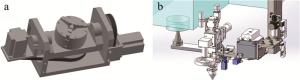
Figure 1. Basic set-up
-
在数控编程中,将CAM软件生成的刀位轨迹计算过程称为前置处理,前置处理以工件坐标系为基准,不考虑具体机床的空间结构、类型以及数控系统,前置处理生成的刀位数据文件不能直接被机床使用。后处理就是根据具体机床控制指令格式、运动结构及其运动空间的范围等,将前置处理生成的刀位数据文件转换成适合于机床各轴的运动数据,后处理流程如图 2所示。
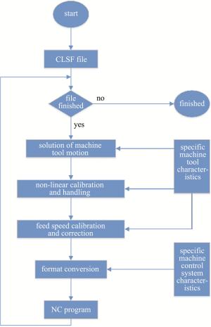
Figure 2. Flow of post-process
实验设备选用HNC-818B五轴数控系统,由于其是“3+2”双工作台回转型结构,市面上无成熟的后处理,亟需开发一款适用于该设备的五轴联动后处理系统。基于UG CAM软件的后处理构造器来构造“3+2”双工作台回转型后处理系统,经过反复实验论证:HNC-818B五轴数控系统与fanuc_6M后处理系统兼容性最好。因此,以fanuc_6M后处理系统为基础,开发适用于本实验设备类型的后处理。
-
通过UG CAM的后处理构造器构建基于“3+2”双工作台回转型五轴联动数控加工设备后处理,部分定义、修改的代码如表 1所示。
Table 1. Post-process code description
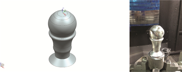
symbol function G00 motion rapid G01 motion linear G04 delay (0.1s~9999.9s) G17 plane xy G41 tool offset right G43 tool length adjust plus M03 spindle clockwise rotation M05 spindle off V the 4th axis, plane of rotation yz, -110°~ 110° U the 5th axis, plane of rotation xy, -360°~ 360° 后处理验证实验以某型号奖杯和叶片为加工案例,通过UG CAD软件构建3维模型,UG CAM编排加工工序,“3+2”双工作台回转型后处理导出程序进行加工,验证该后处理的功能性和适用性。奖杯模型、加工成型件如图 3所示,部分CAM仿真加工轨迹如图 4所示,加工工序如表 2所示。表中,D是直径,R是半径。

Figure 3. Trophy model and physical sample
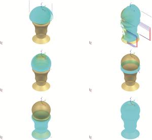
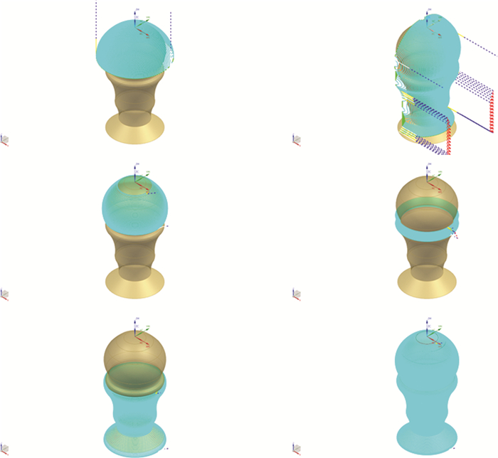
Figure 4. Simulation processing track of the trophy
Table 2. Procedure of trophy processing
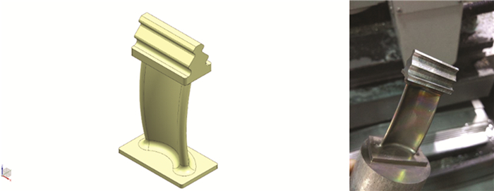
process tool specification driving method feed rate/(mm·min-1) spindle speed/(r·min-1) cavity milling cutter D=10mm automation 500 3000 cavity milling cutter D=10mm automation 500 3000 contour area milling ball cutter R=5mm area milling 600 3500 contour area milling ball cutter R=5mm boundary 500 3500 contour area milling ball cutter R=5mm boundary 500 3500 variable contour milling ball cutter R=2mm curved surface 1500 4500 variable contour milling ball cutter R=5mm curved surface 1200 3500 variable contour milling ball cutter R=5mm curved surface 1200 3500 variable contour milling ball cutter R=2mm curved surface 1500 4500 叶片模型、加工成型件如图 5所示,加工工序如表 3所示,部分CAM仿真加工轨迹如图 6所示。

Figure 5. Blade model and physical sample
Table 3. Blade processing process
process tool specification driving method spindle speed/(r·min-1) feed speed/(mm·min-1) cavity milling customized follow around 2600 400 cavity milling customized follow around 2600 400 cavity milling cutter D=14mm follow around 3200 350 cavity milling cutter D=4mm follow around 4200 400 contour area milling ball cutter R=2mm aera milling 4200 600 variable contour milling ball cutter R=2mm curved surface 4200 1200 cavity milling cutter D=4mm follow around 4200 300 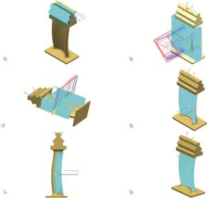
Figure 6. Simulation processing track of blade
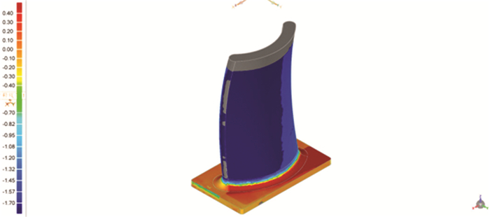
通过FARO激光扫描仪对加工的叶片进行扫描,对比原始3维模型的数据,尺寸误差如图 7所示。误差原因初步的分析结果是:未对加工刀位数据进行补偿处理。

Figure 7. Dimensional error graph
-
由1.3节可知,该“3+2”双工作台回转型五轴联动数控加工设备后处理导出程序只能进行减材加工,无法实现增材制造的功能。因此,还需在后处理器中定义增材制造代码,部分代码如表 4所示。
Table 4. Laser additive manufacturing code description
symbol function S1 laser power, setting range 50W~950W S2 powder feeder, set value range 280g/min~900g/min M83 1# powder feeder on M84 2# powder feeder on M85 powder feeder off M86 laser head goes down to the bottom M87 laser head goes up to the top M88 laser on M89 laser off 基于表 4的代码功能,通过UG CAD设计某型号机匣3维模型,如图 8a所示。目前,该型号机匣通过3种方式成型:(1)铸模成型,机匣整体结构为薄壁件,在熔铸过程中因溶液流动慢、热应力分布不均匀的问题易造成缩孔、微裂纹等缺陷,影响产品的力学性能和表面质量;(2)通过五轴联动铣削加工,在加工过程中易出现零件变形、加工干涉的现象,由于是减材加工,成品质量只占毛坯料质量小于10%,造成材料的极大浪费;(3)通过单一的增材制造模式进行加工,其成型件不可避免的需要辅助以支撑,这些支撑需要通过磨抛、铣削等方式去除,造成加工周期的延长和对零件表面的二次破坏[18-20]。
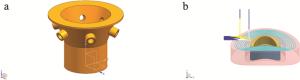
Figure 8. Schematic diagram of receiver part model and ring track
通过五轴联动与激光近净成形的增减材混合制造技术加工该型号机匣,能很好地解决以上3种成型模式中的问题。基于增减材混合制造的加工理念,分析该型号机匣结构可知:圆环与基材结合面是曲面结构,因此,圆环的增减材制造是实现机匣混合制造的最关键工艺,如图 8b所示。
机匣部分增减材混合制造加工工艺参数如表 5、表 6所示。其中,圆环在增材制造过程中,初期与基材结合面用800W功率,待增材层厚至4mm~5mm后,改换600W功率。
Table 5. Additive paraments of hybrid manufacture
tool specification power/
Wroad width/
mmthickness/
mmprocetive
gascoaxial nozzle 800 or 600 0.7~1.2 1~1.5 N2 Table 6. Additive paraments of hybrid manufacture
tool specification cutter D=6mm or ball cutter D=6mm process variable counter milling driving method curved surface cutting thickness 0.05mm rotation speed 3000r/min feed rate 500mm/min 由添加增材制造代码的“3+2”双工作台型五轴联动后处理导出加工程序,进行机匣的增减材混合制造,以验证该后处理系统的功能性和适用性,如图 9所示。其中,圆环混合制造工序为:(1)基于激光近净成形技术,增材制造与基材接合面的圆环,如图 9a所示;(2)基于五轴联动数控加工技术,减材制造与基材接合面的圆环,如图 9b所示;(3)基于激光近净成形技术,增材制造圆环至指定高度,如图 9c所示;(4)基于五轴联动数控加工技术,减材制造圆环至指定高度;(5)重复工序(1)~工序(4), 阵列增材、减材加工圆环,如图 9d所示。

Figure 9. Receiver processed by hybrid manufacture
通过加工效果可知,该增减材混合制造后处理在功能上是可行的。
-
叶轮是涡轮机、汽轮机等装置的关键零件,广泛应用于航天航空、船舶机械、石油化工等领域。以闭式叶轮加工为例,其整体的空间结构较复杂,叶片扭曲较大,由于上、下盖板的存在,内流道和叶片的粗、精加工一直是制造领域的难点,如图 10所示。
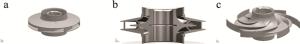
Figure 10. Closed impeller
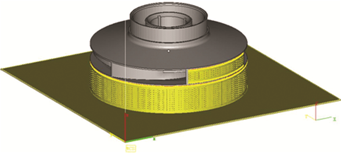
目前,闭式叶轮主要有2种加工方式:(1)铸造与传统机加结合。该方法是目前主流的闭式叶轮制造方法,首先通过铸模制造出整体叶轮,然后通过数控车、铣加工提高叶轮外表面精度。该制造模式易在铸造过程中出现较多的缺陷,如气孔、砂眼、微裂纹等,导致成品率低下,而且由于叶轮上、下盖板的干涉,无法对盖板间的叶片内流道进行铣削和抛磨,导致内流道表面粗糙,进一步导致叶轮工作效率和使用寿命低下;(2)激光增材制造。该方法通过选择性激光熔融(selective laser melting, SLM)3-D打印设备导入闭式叶轮3维模型和点位数据,逐层叠加实现零件的增材制造,优势是零件能一次打印成型,缺点是支撑过多且无法规避(如图 11所示, 其中黄色部分为支撑),后期去支撑工作量较大,耗时且影响内流道表面精度[21]。

Figure 11. Additive manufacturing closed impeller by SLM
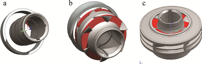
通过实验的增减材混合制造设备开发适用于闭式叶轮加工的新工艺,能很好地解决单一加工模式下易干涉、支撑多的问题。具体工艺流程如下:(1)通过激光近净成型技术在基板上增材制造出轴类、底座等基础件;(2)通过五联动数控加工技术精加工轴类、底座等基础件以提高其表面精度,如图 12a所示; (3)通过旋转轴和直线轴的联合运动,实时改变基础件的运动位置和角度,使待增材制造的部分如叶片、盖板等,能尽可能的少支撑、无支撑;或者待增材制造的部分,3-D打印的支撑便于后期清除,如图 12b所示,红色部分为支撑;(4)通过旋转轴和直线轴的联合运动,实时改变加工区域的位置和角度,分段式地增、减材加工叶轮中的叶片、上下盖板等,如图 12c所示,直至完整的闭式叶轮成型。

Figure 12. Closed impeller processing flow
通过激光近净成形技术和五联动数控加工技术的转换应用,既可有效减少支撑面,提高叶轮制造的效率和精度,亦可在叶轮内流道表面熔覆上功能涂层,实现叶轮的整体寿命和最大功能性。
-
激光近净成形技术可实现对零件表面的涂层修复,延长零件的服役寿命,提高功能零件的力学性能。但是其加工对象以轴类件为主,涂层后需要通过车铣、磨削等机加工方式提高其表面精度,无法实现具有复杂形面结构的零件修复。基于此,将3-D视觉扫描系统与增减材混合制造技术结合,其加工流程如图 13所示。

Figure 13. Scanning, modeling, repairing, etc. flowchart
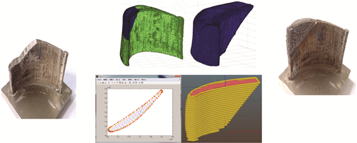
以叶片修复为例,修复过程如图 14所示。首先,通过3-D扫描装置对待修复零件的缺损部位进行扫描,提取点云数据;其次,通过相应软件对缺损部位进行建模、切片、轨迹优化;然后,进行激光近净成形增材制造;最后,通过五轴数控加工技术进行铣削减材加工实现修复区域的高精度。

Figure 14. Blade additive-subtractive material repairing process
-
(1)“3+2”型五轴联动数控机床从设备类型上不属于真正意义上的五轴联动数控机床,它是在传统三轴数控加工设备上集成旋转轴,在功能上实现对零件的五轴联动加工。对于该类型五轴数控机床,市面上无成熟的后处理系统,实验中对于“3+2”型五轴联动数控机床后处理的研究,有一定的借鉴性和通用性。
(2) 实验中以“3+2”型五轴联动数控加工中心为基础装置,在z轴伺服机构上集成激光近净成形增材制造装置,在后处理器中定义激光增材制造代码,实现零件的增减材混合制造。相对于单一模式的减材、增材加工,通过实际的加工案例和应用拓展,论述了增减材混合制造的技术优势。
(3) 本文中对于增减材混合制造的研究,尚有许多需要补充和论证之处未能及时开展。如实际加工零件尺寸与原始数据尺寸的误差补偿措施,未能进一步进行实验论证;实验装置是在五轴联动数控加工中心上集成激光近净成形装置实现增减材混合制造,对于加工过程中的粉末处理(易渗入伺服电机中,造成伺服定位精度不准、漏电等)、冷却循环模式、设备因限位导致的欠切/过切现象等,亦未采取有效措施进行补救。以上这些都是下一步要实现零件增减材精密制造、安全制造、稳定制造的必要措施,也是增减材混合制造技术从实验验证走向工程化生产的重要举措。
五轴联动与激光近净成形的混合制造技术研究
Hybrid manufacturing study based on five-axis linkage and LENS
-
摘要: 为了弥补加工制造技术上的局限性, 在五轴联动计算机数控加工中心的基础上, 采用增减材混合制造的技术方法集成激光近净成形制造装置, 在结构上形成激光增减材混合制造装置; 并基于UG后处理构造器开发增减材混合制造的后处理系统, 在功能上实现对零件的增减材混合制造。结果表明, 可实现复杂金属零件的一次成形, 减少因多次装夹引起的加工误差和低效; 相较于单一的增材、减材加工模式, 产品成品率提高20%以上, 加工时间缩短45%以上, 支撑减少30%以上, 尤其对于有封闭内流道的零件, 其内流道表面精度达到0.6μm, 有效延长零件的服役寿命, 实现了零件弱支撑、无支撑、无干涉、高精度和高效率的加工。该研究可为激光增减材混合制造的工艺方案、制造模式、应用拓展提供参考。Abstract: In order to make up for the limitations of manufacturing technology, laser engineered near shaping (LENS) device was integrated on a five-axis linkage computerized numerical control (CNC) machine by applying the technology of adding and subtracting materials, which forms an equipment realizing additive and subtractive machining structurally; UG post-processing builder was used to develop a post-processing machining system of additive and subtractive materials, which realizes parts' hybrid manufacturing functionally. The results show that hybrid manufacturing can achieve one-time forming for complex metal parts, and reduce machining errors and inefficiencies caused by multiple clamping. Compared with additive or subtractive processing mode, the product yield rate is increased more than 20%, processing time is shortened more than 45%, supporting amount is reduced more than 30%, respectively. Especially for parts with a structure of closed internal flow channel, the surface accuracy of the internal flow channel can reach 0.6μm by using hybrid manufacturing method, which effectively extends parts' service life. Hybrid manufacturing technology can realize processing with weak support, no support, no interference, high-precision and high-efficiency. This research provides reference for the process plan, manufacturing mode, and application expansion of laser hybrid manufacturing.
-
Key words:
- laser technique /
- hybrid manufacturing /
- five-axis linkage /
- laser engineered net shaping /
- post process
-
Figure 9. Receiver processed by hybrid manufacture
a—additive manufacturing the ring on the substrate surface b—subtractive manufacturing the ring on the substrate surface c—additive manufacturing the ring to a specified height d—array of increased and decreased materials manufacturing ring e—receiver sample
Figure 10. Closed impeller
a—3-D model b—cross-sectional view c—3-D model with upper and lower cover removed
Table 1. Post-process code description
symbol function G00 motion rapid G01 motion linear G04 delay (0.1s~9999.9s) G17 plane xy G41 tool offset right G43 tool length adjust plus M03 spindle clockwise rotation M05 spindle off V the 4th axis, plane of rotation yz, -110°~ 110° U the 5th axis, plane of rotation xy, -360°~ 360°  下载: 导出CSV
Table 2. Procedure of trophy processing
process tool specification driving method feed rate/(mm·min-1) spindle speed/(r·min-1) cavity milling cutter D=10mm automation 500 3000 cavity milling cutter D=10mm automation 500 3000 contour area milling ball cutter R=5mm area milling 600 3500 contour area milling ball cutter R=5mm boundary 500 3500 contour area milling ball cutter R=5mm boundary 500 3500 variable contour milling ball cutter R=2mm curved surface 1500 4500 variable contour milling ball cutter R=5mm curved surface 1200 3500 variable contour milling ball cutter R=5mm curved surface 1200 3500 variable contour milling ball cutter R=2mm curved surface 1500 4500
下载: 导出CSV
Table 3. Blade processing process
process tool specification driving method spindle speed/(r·min-1) feed speed/(mm·min-1) cavity milling customized follow around 2600 400 cavity milling customized follow around 2600 400 cavity milling cutter D=14mm follow around 3200 350 cavity milling cutter D=4mm follow around 4200 400 contour area milling ball cutter R=2mm aera milling 4200 600 variable contour milling ball cutter R=2mm curved surface 4200 1200 cavity milling cutter D=4mm follow around 4200 300
下载: 导出CSV
Table 4. Laser additive manufacturing code description
symbol function S1 laser power, setting range 50W~950W S2 powder feeder, set value range 280g/min~900g/min M83 1# powder feeder on M84 2# powder feeder on M85 powder feeder off M86 laser head goes down to the bottom M87 laser head goes up to the top M88 laser on M89 laser off
下载: 导出CSV
Table 5. Additive paraments of hybrid manufacture
tool specification power/
Wroad width/
mmthickness/
mmprocetive
gascoaxial nozzle 800 or 600 0.7~1.2 1~1.5 N2
下载: 导出CSV
Table 6. Additive paraments of hybrid manufacture
tool specification cutter D=6mm or ball cutter D=6mm process variable counter milling driving method curved surface cutting thickness 0.05mm rotation speed 3000r/min feed rate 500mm/min
下载: 导出CSV
-
[1] ZONG X W, XIONG C, ZHANG B, et al. Summary of research on manufacturing complex metal parts based on rapid prototyping techno-logy[J]. Hot Working Technology, 2019, 48(1): 5-8 (in Chinese). [2] XU X P, LI M L, LIU Y Y, et al. Crack analysis of laser engineered net shaping GH99 alloy[J]. Transactions of Materials and Heat Treatment, 2019, 40(2): 1-5 (in Chinese). [3] MIAO P. Effect of deposition efficiency on microstructure and property of 316L stainless steel fabricated by laser engineered net shaping[D]. Dalian: Dalian University of Technology, 2018: 7-21 (in Chinese). [4] LI H B. Research on five-axis linkage dual NURBS interpolation technology[D]. Nanchang: Nanchang Hangkong University, 2019: 8-13(in Chinese). [5] ZHANG Ch Y, CHEN X Sh, SUN X T. The development situation of metal 3-D printing manufacturing technology[J]. Laser Technology, 2020, 44(3): 393-396(in Chinese). [6] HE L. The study on semi-solid metal extrusion deposition molding technology based on five-axis linkage CNC workbench[D]. Wuhan: Huazhong University of Science and Technology, 2015: 11-27 (in Chinese). [7] CAO Ch Ch, GUO P Y, YANG D K. Mechanical structure design of teaching five-axis CNC milling machine based on UG[J]. Agricultu-ral Mechanization Using & Maintenance, 2019, 7: 6-7 (in Chinese). [8] DING H Y, HE J Ch. Research progress in additive manufacturing of high entropy alloys[J]. Journal of Jiangsu University of Science and Technology (Natural Science Edition), 2020, 34(6): 36-39 (in Chinese). [9] ZHAO X K. Research progress of additive manufacturing technology on nickel-titanium memory alloy and its application prospects in aviation[J]. Aeronautical Manufacturing Technology, 2016, 12: 34-40 (in Chinese). [10] ZHONG M L, NING G Q, LIU W J. Research and development on laser direct manufacturing metallic components[J]. Laser Technology, 2002, 26(5): 388-391(in Chinese). [11] DOÑATE-BUENDÍA C, GU D D, SCHMIDT M, et al. On the selection and design of powder materials for laser additive manufacturing[J]. Materials & Design, 2021, 204: 109653. [12] GAO M Q, ZHAO Y H, ZHAO J B, et al. Research status and development of additive/subtractive hybrid manufacturing (A/SHM) [J]. Vacuum, 2019, 56(6): 68-71(in Chinese). [13] HUANG X, ZHANG J Ch, LIAN G F, et al. Research status and application of extreme high speed cladding[J]. Machine Tool & Hydraulics, 2021, 49(6): 151-155(in Chinese). [14] SHI Y, WANG L F, SHI Q, et al. The electrical control systems of high-performance selective laser melting additive manufacturing equipment[J]. Manufacturing Automation, 2019, 43(3): 21-22(in Chinese). [15] GUO Ch H, WANG Z Ch, YAN J Y, et al. Research progress in additive-subtractive hybrid manufacturing[J]. Chinese Journal of Engineering, 2020, 42(5): 540-548(in Chinese). [16] LI A, LIU X F, YU B, et al. Key factors and developmental directions with regard to metal additive manufacturing[J]. Chinese Journal of Engineering, 2019, 41(2): 159-173(in Chinese). [17] YAO R B, YANG L X, DAI L L. Study on hybrid process planning of additive and subtractive manufacturing[J]. Mechanical Science and Technology for Aerospace Engineering, 2018, 37(7): 1076-1081(in Chinese). [18] BROWN D, LI C, LIU Z Y, et al. Surface integrity of Inconel718 by hybrid selective laser melting and milling[J]. Virtual and Physical Prototyping, 2018, 13(1): 27-30. [19] SAMES W J, LIST F A, PANNALA S, et al. The metallurgy and processing science of metal additive manufacturing[J]. International Materials Reviews, 2016, 61(5): 315-316. doi: 10.1080/09506608.2015.1116649 [20] SING S L, AN J, YEONG W Y, et al. Laser and electron-beam powder bed additive manufacturing of metallic implants: A review on processes, materials and designs[J]. Journal of Orthopaedic Research, 2016, 34(3): 369-370. doi: 10.1002/jor.23075 [21] ZHANG J T, ZHANG W, LI Y J, et al. Laser deposition additive-subtractive hybrid manufacturing process for stainless steel powder based on DMG MORI LASERTEC 653D[J]. Materials Science and Engineering Powder Metallurgy, 2018, 23(4): 368-369(in Chinese). -

 点击查看大图

计量
- 文章访问数: 5053
- HTML全文浏览量: 3905
- PDF下载量: 19
- 被引次数: 0
