 网站地图
网站地图


-
随着现代各种电子元器件的微型化、复杂化以及对高温高压条件敏感,封装尺寸已经演变为微米级,如何实现封装以及提高气密封装的密封性,成为封装领域的一大挑战。玻璃因其良好的机械性能、化学稳定性、耐腐蚀性、高透光率等特点,在封装领域和真空玻璃连接领域得到广泛重视[1]。激光加热熔融玻璃料进行玻璃焊接技术具有高效率、高焊接质量以及加热位置可控等优点,被广泛运用于微器件封装、半导体封装及太阳能电池封装等领域[2-5]。在玻璃激光焊接中,焊缝中的气孔[6]和玻璃料未完全熔融[7]是最常见的两种缺陷,会对封装气密性和封装强度产生一定的影响。
玻璃激光焊接技术利用玻璃料对激光的热吸收,使玻璃料熔融并重新凝固来实现上下玻璃板的连接[8-11]。在焊接过程中,高质量的焊缝很大程度上取决于焊接时的工艺参数。目前已有的研究主要都集中在讨论不同工艺参数对焊缝剪切强度和残余应力的影响[12-14],对焊缝中气孔和玻璃料未熔区域的产生和抑制研究较少。气孔大量存在容易产生应力集中,形成裂纹,降低焊接质量,减少气孔率会显著提高焊缝连接强度和气密性[15]。焊缝两端未熔区域的存在会减小焊缝有效连接面积,降低焊缝强度。在玻璃激光焊接中,焊缝中气孔和未熔区域所占面积比率越大,焊缝连接质量就会越差,因此,预测和抑制玻璃激光焊接过程中气孔和未熔区域的产生对提高焊接质量具有重要意义。
响应面法(response surface method, RSM)是一种参数优化问题的数学和统计分析方法,该方法被广泛用于优化焊接工艺参数[16-18]。在玻璃激光焊接过程中,气孔和未熔区域的存在往往取决于预烧结峰值温度、激光功率、焊接速率以及离焦量。为了预测和抑制焊缝气孔和未熔区域的产生,采用响面法建立玻璃激光焊接后焊缝缺陷面积占比率与焊接工艺参数的数学模型,研究各工艺参数对焊缝缺陷面积占比率的影响规律。通过工艺参数优化验证了模型的正确性,有效降低了焊缝气孔和未熔区域的产生,提高了焊缝连接强度。
-
如图 1所示,自行搭建的激光实验平台由激光器、3维平台、夹具平台、同轴观测系统和数控系统组成。激光器采用RFL-DDL-100型半导体激光器,光束辐射波长为915nm±10nm,聚焦镜焦距为300mm, 光斑直径为300μm,最大输出功率为100W。

Figure 1. Glass laser welding test platform
在玻璃激光焊接过程中,基板和盖板均选用美国康宁公司的40mm×40mm×0.7mm Eagle XG玻璃板。Eagle XG玻璃板是硼硅酸盐玻璃,具有高表面质量、热稳定性、低密度以及高耐化学腐蚀性。玻璃料选用BASS公司的高温类型,对近红外激光有良好的吸收性。玻璃和玻璃料的物理性质如表 1所示。
Table 1. Physical properties of glass and glass frit
material transition temperature/℃ softening point/℃ coefficient of thermal expansion/ 10 -7℃-1 glass substrate 722 971 31.7 glass frit 343 428 48 -
玻璃激光焊接的流程图如图 2a所示。(1)将配置好的玻璃料通过丝网印刷沉积在玻璃基板上;(2)将丝印玻璃料的玻璃基板放进加热炉进行预烧结,去除挥发性添加剂并使玻璃料平整地固化在玻璃基板上;(3)将玻璃盖板和基板对齐进行焊接,中间玻璃料层吸收激光能量变为熔融状态,在夹具压力的作用下玻璃料与上下玻璃板之间形成粘合。焊接过程如图 2b所示。焊接样品图如图 3所示。

Figure 2. a—flow chart of glass laser welding b—schematic diagram of glass laser welding

Figure 3. Glass laser welding
玻璃激光焊接焊缝必须具备一定的连接强度,才能满足电子元器件的使用要求,本文中使用剪切强度代表焊缝的连接强度。当焊缝成形良好、气孔较少时,剪切强度通常比较高,当焊缝存在熔融不充分、气孔等缺陷时,剪切强度通常会比较低。按照美军标MIL-STD-883G, 焊缝剪切强度达到6.25MPa即可视为焊缝连接质量良好。测试试件示意图如图 4所示。测试试件焊缝为0.8mm×30mm。对试件上下两端施加压力,直至焊缝断裂,根据剪切力计算可得剪切强度。

Figure 4. Schematic diagram of weld shear strength test
玻璃料的预烧结工艺是进行玻璃激光焊接前的最后一道工序,预烧结温度会对最终玻璃焊接效果有很大影响。丝印玻璃料的玻璃板预烧结温度变化曲线如图 5所示。第一阶段加热除去玻璃料中含有的水;第二阶段加热通过蒸发或燃烧的方式去除掉玻璃料中的有机粘结剂; 第三阶段,设置预烧结峰值温度,以5℃/min的速率将玻璃料加热至峰值温度并保温30min, 使得玻璃料在玻璃板上软化,最后在炉内将玻璃板缓慢降至室温,避免出现应力集中。影响预烧接的因素有升温速率、降温速率、预烧结峰值温度以及各阶段保温时间等,其中预烧结峰值温度是影响焊接质量的主要因素[19]。

Figure 5. Pre-sintering curve of glass frit
在玻璃激光焊接过程中,气孔主要来源于两个方面: (1)玻璃粉间隙中的空气[20]; (2)玻璃粉中的部分物质分解气化产生的气体,气体无法及时溢出形成气孔。玻璃料未熔区域的产生主要与激光输入能量有关,当能量足够高时,玻璃料会充分熔化,在压力的作用下完全铺展开形成焊缝,焊缝宽度较之前玻璃料宽度明显增大,但过高的激光输入能量也会使部分物质分解气化产生气体,较大的焊缝宽度不利于气体溢出,从而形成大尺寸的密集型气孔,如图 6a所示。当激光输入能量较低时,焊缝中部存在少量气孔,焊接良好,但由于激光能量呈高斯分布,焊缝边缘能量不足,玻璃料两端未完全熔化形成有效连接,如图 6b所示。

Figure 6. Topography of weld defect
玻璃激光焊接后使用金相显微镜放大200倍观测焊缝气孔和未熔区域分布特征,沿焊缝长度方向在5mm~35mm之间分5段取样。采用Image J图像分析软件对5段样品的金相照片处理后得到焊缝中气孔面积和未熔融区域面积之和,求其平均值。定义焊缝中气孔面积和未熔区域面积之和与焊缝总面积的比值为焊缝缺陷面积占比率。
本文中通过的Box-Behnken设计方法确定预烧结峰值温度、激光功率、焊接速度以及离焦量对焊缝缺陷面积占比率影响的试验方案。工艺参数取值范围如表 2所示。设计实验共29组,具体的实验方案及结果见表 3。
Table 2. Process parameters and design level
limits pre-sintering peak temperature T/℃ laser power P/W welding speed v/(m·min-1) defocusing amount D/mm -1 430 35 0.07 13 0 480 38 0.10 15 1 530 41 0.13 17 Table 3. Surface response test table
number pre-sintering peak temperature T/℃ laser power P/W welding speed v/(m·min-1) defocusing amount D/mm proportion of weld defects area L/% 1 430 35 0.1 15 2.366 2 530 35 0.1 15 13.843 3 430 41 0.1 15 10.304 4 530 41 0.1 15 4.031 5 480 38 0.07 13 16.364 6 480 38 0.13 13 16.551 7 480 38 0.07 17 19.436 8 480 38 0.13 17 30 9 430 38 0.1 13 8.016 10 530 38 0.1 13 23.233 11 430 38 0.1 17 10.559 12 530 38 0.1 17 18 13 480 35 0.07 15 0.532 14 480 41 0.07 15 30.544 15 480 35 0.13 15 31 16 480 41 0.13 15 3.255 17 430 38 0.07 15 15.325 18 530 38 0.07 15 7.618 19 430 38 0.13 15 2.109 20 530 38 0.13 15 18.431 21 480 35 0.1 13 1.516 22 480 41 0.1 13 28.293 23 480 35 0.1 17 33 24 480 41 0.1 17 11.925 25 480 38 0.1 15 2.635 26 480 38 0.1 15 7.541 27 480 38 0.1 15 9.1604 28 480 38 0.1 15 3.412 29 480 38 0.1 15 3.427 -
对实验数据进行拟合,建立二次多项式回归模型。对拟合模型进行方差分析,剔除对焊缝缺陷面积占比率影响不显著的项,结果如表 4所示。p值的大小代表模型和因素的显著水平,p值小于0.05表示该项显著。模型的F值为18.88,p值小于0.0001,意味着模型极显著。失拟项的p值为0.3319,其值大于0.05,说明方程与实际拟合误差小,回归性较好。相关性分析可得拟合度R2=0.9243, 接近于1,预测的拟合度Rp2=0.8039和修正的拟合度Ra2=0.8754接近,信噪比RSNR=14.318远大于4,这些数值表明模型符合要求,预测可信度良好。
Table 4. Analysis of variance of the proportion of weld defect area
source sum of squares degree of freedom mean square F value p value model 2664.37 11 242.22 18.88 < 0.0001 significant T/℃ 110.88 1 110.88 8.64 0.0092 P/W 3.10 1 3.10 0.24 0.6296 v/(mm·min-1) 11.07 1 11.07 0.86 0.3659 D/mm 69.83 1 69.83 5.44 0.0322 TP 78.77 1 78.77 6.14 0.0240 Tv 144.35 1 144.35 11.25 0.0038 Pv 833.97 1 833.97 64.99 < 0.0001 PD 572.45 1 572.45 44.61 < 0.0001 P2 107.81 1 107.81 8.40 0.0100 v2 290.63 1 290.63 22.65 0.0002 D2 644.61 1 644.61 50.24 < 0.0001 lack of fit 184.06 13 14.16 1.66 0.3319 not significant R2 0.9243 Ra2 0.8754 Rp2 0.8039 RSNR 14.318 从表 4可以看出,一次项中的T(预烧结峰值温度)、D(离焦量),交互项中的TP(预烧结峰值温度和激光功率)、Tv(预烧结峰值温度和焊接速率)、Pv(激光功率和焊接速率)、PD(激光功率和离焦量),以及2阶值P2,v2和D2对模型都是显著的,判断可知,各工艺参数对于焊缝缺陷面积占比率的影响不是简单线性关系。对实验数据进行拟合,得到回归模型:
$ \begin{array}{c} L = - 879.707 + 0.784T + 26.515P + 2745.656v + \\ 3.556D - 0.0296TP + 4.005Tv - 160.436Pv - \\ 1.994PD + 0.445{P^2} + 7303.08{v^2} + 2.447{D^2} \end{array} $
(1) 式中,L为焊缝缺陷面积占比率。
-
图 7反映了工艺参数对焊缝焊缝缺陷面积占比率的影响趋势。结合方差分析观察可知,相比于激光功率P和焊接速率v,预烧结峰值温度T与离焦量对焊缝焊缝缺陷面积占比率D影响更为显著。焊缝缺陷面积占比率L随着预烧结峰值温度的升高不断升高,随着离焦量、激光功率和焊接速度的增加先升高后降低。

Figure 7. Influence trend of process parameters on the proportion of weld defects area
图 8是预烧结峰值温度与激光功率对焊缝缺陷面积占比率率影响趋势的3维响应曲面图。图 9是预烧结峰值温度与焊接速率对焊缝缺陷面积占比率影响趋势的3维响应曲面图。从图中可以看出,当激光功率较低、预烧结峰值温度较高时或焊接速率较快、预烧结峰值温度较高时,焊缝缺陷面积占比率比较高。这是因为随着预烧结峰值温度的持续上升促使玻璃料形成结构坚硬的共晶产物,造成玻璃料流动性下降,留下大量的孔洞。而焊接过程中低激光功率或高焊接速率使玻璃料能量输入降低,玻璃料难以充分熔化,粘度较大,流动困难,空隙无法得到填补形成气孔,使焊缝缺陷面积占比率升高。

Figure 8. Effect of pre-sintering peak temperature and laser power on the proportion of weld defects area

Figure 9. Effect of pre-sintering peak temperature and welding speed on the proportion of weld defects area
图 10中的3维响应曲面显示了激光功率与焊接速率对焊缝缺陷面积占比率的共同影响趋势。两者的交互作用对于焊缝缺陷面积占比率的影响较强。当激光功率较低、焊接速率较快时,焊缝缺陷面积较大。这是因为在低功率时激光能量较低,高焊接速率又大大缩短了激光照射在玻璃料上的时间,导致输入线能量过低,使玻璃料沿宽度方向两端未完全熔融面积增加,焊缝缺陷面积占比率升高。线能量是激光功率与焊接速率的比值,定义为单位长度焊缝上的激光输入能量。

Figure 10. Effect of laser power and welding speed on the proportion of weld defects area
当激光功率较高、焊接速率较慢时,焊缝缺陷面积占比率也很高,这是因为线能量过高,玻璃料加速流动,使小气泡迅速汇集成大气泡,玻璃粉中部分物质也会随着高能量的持续输入分解气化形成大气泡,并且焊缝充分铺展开来形成宽焊缝阻碍气泡的溢出,待玻璃料凝固后形成大气孔。因此, 只有当激光功率较低、焊接速率较慢或激光功率较高、焊接速率较快时,可以获得有利的线能量,此时玻璃料恰好熔融,粘度降低,润湿性增强,铺展的更为平整,焊缝缺陷面积占比率明显降低。
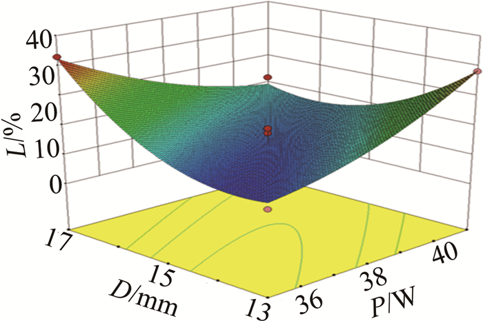
图 11中的3维响应曲面显示了激光功率和离焦量对焊缝缺陷面积占比率的共同影响规律。离焦量的变化会改变激光光斑的大小,离焦量越小,激光的光斑直径越小,能量越集中。当激光功率较低、离焦量较大时,激光功率密度低,玻璃料未完全熔化,黏度较大,影响玻璃料颗粒间的残留气体溢出,焊缝缺陷面积占比率升高。当激光功率较高、离焦量较低时,输入到玻璃料中的能量过于集中,玻璃料过热使部分物质分解气化产生气体形成气孔,焊缝缺陷面积占比率升高。

Figure 11. Effect of laser power and defocusing amount on the proportion of weld defects area
-
在玻璃激光焊接过程中,焊缝中气孔和未熔区域的存在会减小焊缝的有效连接面积和气密性,使焊接接头的连接强度下降,但在实验过程中,难以做到完全同时避免这两类缺陷的存在,因此作者认为焊缝缺陷面积占比率小于1%的焊缝已经是一条良好的焊缝。在工艺参数取值范围内,设置以获得小于1%的焊缝缺陷面积占比率为优化准则,获得多组优化结果。由于设备精度问题,从优化结果中选择满意度高的优化参数组合取整后(T=440℃,P=37W,v=0.1m/min,D=14.4mm)进行3组玻璃激光焊接实验。结果显示, 焊缝缺陷面积占比率平均值为0.512%,实际值和预测值(0.382%)较为吻合。证明模型准确,根据该模型优化出的工艺参数合理。
-
在玻璃激光焊接优化工艺参数下进行焊接试验研究。使用金相显微镜对样件进行观察。如图 12所示,焊缝成形良好,厚度约为2.41μm,表面平整,组织致密,说明玻璃料在激光作用下熔融充分,铺展良好,焊缝具有较好的金相组织,焊缝中虽有少量气孔,但气孔直径极小相互不连通且分布均匀,力学性能良好。

Figure 12. Weld morphology under optimized parameters
对样件进行剪切强度测试,结果如图 13所示。发现断裂发生在玻璃母材处,说明玻璃料充分熔融并扩散到玻璃板中。记录施加压力过程中的压力最大值为焊缝能承受的最大剪切力。采用优化所得的工艺参数值进行5次实验,对5个试件进行剪切力测试,剪切力的均值为415.68N,焊缝剪切强度为17.765MPa。说明在该模型下优化出的工艺参数比较合理,焊缝缺陷面积占比率低,连接质量良好。

Figure 13. The actual picture taken at the weld fracture
-
采用响应面法建立了玻璃激光焊接过程中不同工艺参数与焊缝缺陷面积占比率之间的数学模型。
(1) 相比于激光功率和焊接速率,预烧结峰值温度与离焦量对焊缝中气孔和未熔区域的产生影响更为显著,焊缝缺陷面积占比率随着预烧结峰值温度的升高不断升高,随着离焦量、激光功率和焊接速率的增加先升高后降低。
(2) 当预烧结峰值温度过高时,激光功率较低或焊接速率较快都会促使焊缝缺陷面积占比率升高。激光功率-焊接速度以及激光功率-离焦量的交互作用对焊缝缺陷面积占比率影响极为显著,这3个参数控制着焊缝的能量输入,焊缝单位时间内单位面积上的合适的能量输入有利于玻璃料充分熔融并降低气孔的产生。
(3) 对工艺参数进行优化并进行试验验证。结果表明, 优化工艺参数下焊缝表面形貌良好,焊缝缺陷面积占比率接近预测结果,样件焊缝剪切强度为17.765MPa,高于标准值,焊缝断裂在母材上,证明焊缝连接强度足够,说明该模型优化出的工艺参数合理。
基于响应面法的玻璃激光焊接焊缝及气孔研究
Research on the weld and pores of glass laser welding based on response surface method
-
摘要: 为了获得气孔率低、玻璃料完全熔化、形貌良好的焊缝, 采用响应面法中的设计原理, 建立了玻璃激光焊接中焊缝缺陷面积占比率与工艺参数(预烧结峰值温度、激光功率、焊接速率和离焦量)的数学模型。基于所建模型, 理论分析了各工艺参数对焊缝缺陷面积占比率的交互影响趋势, 并对工艺参数进行了优化。结果表明, 在预烧结峰值温度为440℃、激光功率为37W、焊接速率为0.1m/min、离焦量为14.4mm的优化参数下进行实验, 焊缝中气孔面积和玻璃料未完全熔融面积之和仅占焊缝总面积的0.512%, 与模型预测结果吻合, 焊缝表面形貌良好, 焊缝剪切强度为17.765MPa, 高于标准值。该模型优化出的工艺参数是合理的, 该研究有助于提高玻璃激光焊接质量。Abstract: In order to obtain welds with low porosity, complete melting of the glass frit, and good morphology, a mathematical model was established according to the Box-Behnken design principle in the response surface method to study the proportion of weld defects in the glass laser welding and the process parameters including pre-sintering peak temperature, laser power, welding speed, and defocus. Based on this model, the interactive influence trend of each process parameter on the proportion of weld defect area was analyzed, and then the process parameters were optimized. The experimental verification was carried out under the optimized conditions of pre-sintering peak temperature 440℃, laser power 37W, welding speed 0.1m/min, and defocusing distance 14.4mm.The results show that the sum of the pore area and the incomplete melting area of the frit accounts for only 0.512% of the total weld area under the optimized process parameters. The experimental results are consistent with the model predictions. The weld surface morphology is good, and the weld shear strength is 17.765MPa, which is higher than the standard value, indicating that the optimized process parameters under the model are reasonable.
-
Figure 2. a—flow chart of glass laser welding b—schematic diagram of glass laser welding
Figure 6. Topography of weld defect
a—large size dense pores b—the glass frit is not completely melted at both ends
Figure 7. Influence trend of process parameters on the proportion of weld defects area
Figure 8. Effect of pre-sintering peak temperature and laser power on the proportion of weld defects area
Figure 9. Effect of pre-sintering peak temperature and welding speed on the proportion of weld defects area
Figure 10. Effect of laser power and welding speed on the proportion of weld defects area
Figure 11. Effect of laser power and defocusing amount on the proportion of weld defects area
Figure 12. Weld morphology under optimized parameters
a—front side micrograph of weld b—micrograph of weld cross section
Table 1. Physical properties of glass and glass frit
material transition temperature/℃ softening point/℃ coefficient of thermal expansion/ 10 -7℃-1 glass substrate 722 971 31.7 glass frit 343 428 48  下载: 导出CSV
Table 2. Process parameters and design level
limits pre-sintering peak temperature T/℃ laser power P/W welding speed v/(m·min-1) defocusing amount D/mm -1 430 35 0.07 13 0 480 38 0.10 15 1 530 41 0.13 17
下载: 导出CSV
Table 3. Surface response test table
number pre-sintering peak temperature T/℃ laser power P/W welding speed v/(m·min-1) defocusing amount D/mm proportion of weld defects area L/% 1 430 35 0.1 15 2.366 2 530 35 0.1 15 13.843 3 430 41 0.1 15 10.304 4 530 41 0.1 15 4.031 5 480 38 0.07 13 16.364 6 480 38 0.13 13 16.551 7 480 38 0.07 17 19.436 8 480 38 0.13 17 30 9 430 38 0.1 13 8.016 10 530 38 0.1 13 23.233 11 430 38 0.1 17 10.559 12 530 38 0.1 17 18 13 480 35 0.07 15 0.532 14 480 41 0.07 15 30.544 15 480 35 0.13 15 31 16 480 41 0.13 15 3.255 17 430 38 0.07 15 15.325 18 530 38 0.07 15 7.618 19 430 38 0.13 15 2.109 20 530 38 0.13 15 18.431 21 480 35 0.1 13 1.516 22 480 41 0.1 13 28.293 23 480 35 0.1 17 33 24 480 41 0.1 17 11.925 25 480 38 0.1 15 2.635 26 480 38 0.1 15 7.541 27 480 38 0.1 15 9.1604 28 480 38 0.1 15 3.412 29 480 38 0.1 15 3.427
下载: 导出CSV
Table 4. Analysis of variance of the proportion of weld defect area
source sum of squares degree of freedom mean square F value p value model 2664.37 11 242.22 18.88 < 0.0001 significant T/℃ 110.88 1 110.88 8.64 0.0092 P/W 3.10 1 3.10 0.24 0.6296 v/(mm·min-1) 11.07 1 11.07 0.86 0.3659 D/mm 69.83 1 69.83 5.44 0.0322 TP 78.77 1 78.77 6.14 0.0240 Tv 144.35 1 144.35 11.25 0.0038 Pv 833.97 1 833.97 64.99 < 0.0001 PD 572.45 1 572.45 44.61 < 0.0001 P2 107.81 1 107.81 8.40 0.0100 v2 290.63 1 290.63 22.65 0.0002 D2 644.61 1 644.61 50.24 < 0.0001 lack of fit 184.06 13 14.16 1.66 0.3319 not significant R2 0.9243 Ra2 0.8754 Rp2 0.8039 RSNR 14.318
下载: 导出CSV
-
[1] HUANG M H, ZHANG Q M, LV Q T, et al. UV-laser welding process of copper-plated glass[J]. Chinese Journal of Lasers, 2020, 47(10): 1002007(in Chinese). doi: 10.3788/CJL202047.1002007 [2] PANG J W, WANG Ch, CAI Y K. Research progress of laser processing technology for glass materials[J]. Laser Technology, 2021, 45(4): 417-428(in Chinese). [3] FERNANDO R, JOSE M, RUI C, et al. Laser assisted glass frit sealing of dye-sensitized solar cells[J]. Solar Energy Materials and Solar Cells, 2012, 96: 43-49. doi: 10.1016/j.solmat.2011.09.009 [4] TAO W, MA Y A, CHEN Y B. The influence of adhesive viscosity and elastic modulus on laser spot weld bonding process[J]. International Journal of Adhesion and Adhesives, 2014, 51: 111-116. doi: 10.1016/j.ijadhadh.2013.12.003 [5] TIAN R, CAO F, LI Y, et al. Application of laser-assisted glass frit bonding encapsulation in all inorganic quantum dot light emitting devices[J]. Molecular Crystals and Liquid Crystals, 2018, 676(1): 59-64. doi: 10.1080/15421406.2019.1595698 [6] FU K, LI Y, YIN L Q, et al. Effect of CuO on laser absorption in glass to glass laser bonding[C]//2014 15th International Conference on Electronic Packaging Technology. New York, USA: IEEE, 2014: 484-488. [7] BEDJAOUI M, AMIRAN J, BRUN J. Ultrathin glass to ultrathin glass bonding using laser sealing approach[C]//2019 IEEE 69th Electronic Components and Technology Conference (ECTC). New York, USA: IEEE, 2019: 995-1001. [8] SEYEDALI E, JORGE M, LUISA A, et al. Low temperature herme-tic laser-assisted glass frit encapsulation of soda-lime glass substrates[J]. Optics and Lasers in Engineering, 2017, 96: 107-116. [9] WU Q, LORENZ N, CANNON K M, et al. Glass frit as a hermetic joining layer in laser based joining of miniature devices[J]. IEEE Transactions on Components and Packaging Technologies, 2010, 33(2): 470-477. doi: 10.1109/TCAPT.2010.2045000 [10] RUI C, ALEXANDRE J D C R, MAÇAIRA J F R, et al. Glass-glass laser-assisted glass frit bonding[J]. IEEE Transactions on Components, Packaging and Manufacturing Technology, 2012, 2(12): 1949-1956. doi: 10.1109/TCPMT.2012.2212195 [11] LORENZ N, MILLAR S, DESMULLIEZ M, et al. Hermetic glass frit packaging in air and vacuum with localized laser joining[J]. Journal of Micromechanics and Microengineering, 2011, 21: 045039. doi: 10.1088/0960-1317/21/4/045039 [12] LOGUNOV S, MARJANOVIC S, BALAKRISHNAN J. Laser assisted frit sealing for high thermal expansion glasses[J]. Journal of Laser Micro Nanoengineering, 2012, 7(3): 326-333. doi: 10.2961/jlmn.2012.03.0017 [13] ZHANG J H, YIN L Q, LI Y, et al. Experimental study about the effect of frit thickness on the residual stress of glass/glass laser bonding[J]. Optical Engineering, 2017, 56(8): 083103. [14] XIAO Y Y, WANG W, WU X Y, et al. Process design based on temperature field control for reducing the thermal residual stress in glass/glass laser bonding[J]. Optics & Laser Technology, 2017, 91: 85-91. [15] MIAO H, HE Q, ZHANG Sh W, et al. Study on pores control of vacuum plate glazing by laser sealing[J]. Laser Technology, 2019, 43(1): 38-42(in Chinese). [16] LIANG E B, HU Sh S, WANG Zh J. Optimization of GTAW cladding process of Inconel 625 on carbon steel using response surface methodology[J]. Acta Welding Sinica, 2016, 37 (6): 85-88(in Chinese). [17] WANG W, XIAO Y Y, WU X Y, et al. Optimization of laser-assisted glass frit bonding process by response surface methodology[J]. Optics & Laser Technology, 2016, 77: 111-115. [18] CHEN G Y, WANG B, ZHONG P X, et al. Laser scanning welding of 2060 Al-Li alloy with filler wire[J]. Transactions of the China Welding Institution, 2020, 41(4): 44-50(in Chinese). [19] FU K, LI Y, ZHANG J H. The effect of presintering temperature on laser bonding[J]. Materials Guide: Nano and New Materials, 2014, 28(2): 114-116(in Chinese). [20] CHEN G Y, HE J, ZHONG P X, et al. Study on the porosity control during laser welding of glass[J]. Laser Technology, 2021, 45(3): 286-291(in Chinese). -

 点击查看大图

计量
- 文章访问数: 2819
- HTML全文浏览量: 1812
- PDF下载量: 22
- 被引次数: 0
