 网站地图
网站地图


-
激光多普勒测振因其分辨率高、非接触等优势成为了当前测振的重要技术[1-3]。激光多普勒测振主要应用于微弱振动的测量,在纳米级振动测量中拥有绝对的优势[4-5]。反正切解调算法是当前解算多普勒相位的主要算法,通过解算相位进而解析出目标振动信息(位移、速度、加速度、振幅、频率等)[6-8]。在现场可编程门阵列(field-programmable gate array,FPGA)内通过坐标旋转数字计算方法(coordinate rotation digital computer,CORDIC)解调目标振动产生的调制相位是目前普遍采用的技术方法[9-11]。当振动目标振幅超过激光波长λ的1/4时,解调相位发生周期性跳变,使得测振范围受限。随着激光测振仪校准国际标准ISO-11 1999和ISO-41 2011[12]的提出,为增大振动的测量范围,在反正切解算后,通过相位解缠获取正确相位值[13-15]。
受传统相位解缠算法原理的限制,相位解缠算法在FPGA内实现需占用过多的逻辑资源且只能应用于跳变次数已知情形,本文作者提出一种基于FPGA的自动相位解缠算法。该算法采用流水线结构,通过状态机自动寻求跳变周期数,由跳变周期数实现自动相位补偿,与传统相位解缠算法相比,能够有效节省FPGA的内部资源,扩大振动测量的范围。
-
目标振动对中频信号的相位产生的调制,通过正交混频及低通滤波后,由反正切计算出目标振动产生的相位φ(t)[16]:
$ \varphi (t) = \arctan \left( {\frac{{{u_Q}(t)}}{{{u_I}(t)}}} \right) = \frac{{4\pi }}{\lambda }s(t) $
(1) 式中,uQ(t)为Q路滤波后低频信号;uI(t)为I路滤波后低频信号;λ为激光波长;s(t)为目标振动信号, t表示时间。
在FPGA内计算反正切,有查找表法和CORDIC算法;由于查找表法占用资源多、精度低且速度慢[17-18],通常采用CORDIC算法。采用CORDIC算法的向量模式计算反正切,通过象限转换[19],相位角度范围可扩展到整个圆周,因此φ(t)的取值范围为(-π, π)。当目标振动幅度超过λ/4时,相位以2π为周期发生跳变[20-22], 即:
$ \varphi (t) = \arctan \left( {\frac{{{u_Q}(t)}}{{{u_l}(t)}}} \right) + 2n\pi = \frac{{4\pi }}{\lambda }s(t), (n \in {\bf{Z}}) $
(2) 式中,n为解调相位以2π为周期的跳变次数,取正整数;n增加1,目标振动的位移发生λ/2的变化。
在FPGA内实现相位解缠,设i表示采样相位点,则需通过对相邻相位点相位差值φ(i)-φ(i-1)与阈值π比较,实现相位补偿。
$ \varphi (i) = \left\{ {\begin{array}{*{20}{l}} {\varphi (i) - 2{\pi}, (\varphi (i) - \varphi (i - 1) > {\pi})}\\ {\varphi (i) + 2{\pi}, (\varphi (i) - \varphi (i - 1) < - {\pi})} \end{array}} \right. $
(3) 以6次相位跳变为例,其相位跳变补偿如图 1所示。需要进行连续六轮次的相位补偿算法操作,每次补偿,跳变的相位值变化±2π。

图 1 6次跳变相位补偿图
Figure 1. Phase compensation diagram of six jumps
该相位解缠算法在应用中存在以下局限性:(1)如果存在相位跳变,则需事先知道相位跳周期数方能进行正确的相位补偿;(2)需要对每一轮次补偿后的数据进行缓存,以进行下一轮次相位补偿;(3)在FPGA内实现结构复杂,随着跳变周期数增加,占用资源急剧增加,只适用于跳变周期数较少的情况。
-
为解决相位解缠算法的局限性,根据测振相位跳变规律,在FPGA内设计跳变周期数统计模块和相位解缠模块。其中跳变周期数统计模块实时统计跳变周期数,作为输入参量送到相位解缠模块;相位自动解缠模块依据跳变周期数和跳变位序K,对原始相位数据进行解缠,获得正确的相位信息。
跳变周期数统计,由图 2可知,当不存在跳变时,CORDIC相邻两个输出数据是“连续”变化的,当存在相位跳变时,相邻两点相位输出数据变化2π;即可通过相邻两点相位差值丨φ(i)-φ(i-1)丨与阈值π比较,大于π时,存在跳变。统计相位跳变数N时,可通过φ(i)-φ(i-1)与π比较。
$ N = \left\{ {\begin{array}{*{20}{l}} {N + 1, (\varphi (i) - \varphi (i - 1) > \pi )}\\ {N, ({\rm{ else }})} \end{array}} \right. $
(4) 
图 2 2~10次相位跳变形式
Figure 2. Form of two to ten phase jumps
相位跳变周期数Nc与检测到的相位跳变数N之间的关系如下式所示:
$ {N_{\rm{c}}} = N/2 $
(5) 相位跳变周期数确定流程如图 3所示。FPGA内相位跳变周期数统计模块设计如图 4所示。

图 3 跳变周期数确定流程
Figure 3. Flow chart for determining the number of jump cycles

图 4 FPGA跳变周期数模块
Figure 4. Module of FPGA jump cycle number
通过通用串行总线(universal serial bus,USB) (Cypress USB Console软件)输出相位跳变周期数,验证该检测相位跳变周期数算法的准确性,当设置相位跳变周期数为0~5次时,由该算法检测到的相位跳变周期数如图 5所示。

图 5 相位跳变周期数检测
Figure 5. Detection of phase jump cycle
相位解缠模块是在确定相位跳变周期数的基础上,实现相位的自动补偿。在FPGA内使用偏移码对相位数据进行补偿处理。为了避免补偿后相位数据出现负值,先对相位进行φ(i)+π处理。补偿模块采用状态机设计。其中前两个状态,状态1:φ(i)-φ(i-1) < -π; 状态2:φ(i)-φ(i-1)>π用于找到跳变位序为零的相位点,此后便进入补偿状态; 在状态3时,相邻两相位值φ(i)-φ(i-1) < -π,将i之后的相位值上移2π,变量K记录实时跳变位序,当存在多次跳变时,由跳变位序确定相位上移周期数, 其相位补偿方程为:
$ {\varphi _{\rm{s}}}(i) = 2K\pi + \varphi (i) $
(6) $ K \le 2{N_{\rm{c}}} - 1 $
(7) 式中, φs(i)为补偿后的相位,以4次相位跳变为例,在状态3时其补偿方式示意图如图 6所示。图中0~12π为上移周期数。

图 6 φ(i)-φ(i-1) < -π状态时补偿示意图
Figure 6. Schematic diagram of compensation when φ(i)-φ(i-1) < -π state
当出现φ(i)-φ(i-1)>π时,由状态3转换到状态4。在状态4时,相位补偿上移、下移的周期数,由跳变周期数Nc与跳变位序K共同确定。当跳变位序K < (2Nc-2)时,将i之后的相位值上移;当跳变位序K=(2Nc-2)时,i之后的相位值不变;当跳变位序K>(2Nc-2)时,i之后的相位值下移。其原理如图 7所示。

图 7 φ(i)-φ(i-1)>π状态时补偿示意图
Figure 7. Schematic diagram of compensation when φ(i)-φ(i-1)>π state
由此可得其相位补偿方程为:
$ {\varphi _{\rm{s}}}(i) = \left( {2{N_{\rm{c}}} - 2 - K} \right)2 {\pi} + \varphi (i) $
(8) 对补偿后的相位进行零位校正(如图 8所示),校正后的相位φa(i)为:
$ {\varphi _{\rm{a}}}(i) = {\varphi _{\rm{s}}}(i) - \left( {2{N_{\rm{c}}} - 1} \right){\pi} - {2^{W - 1}} $
(9) 
图 8 相位补偿零点校正
Figure 8. Zero correction for phase compensation
式中,W代表相位数据位宽(16 bit)。
该相位解缠算法状态转化示意图如图 9所示。图中S1、S2、S3、S4表示状态机的4个状态,reset为系统复位信号,reset=1表示系统复位。

图 9 相位解缠算法状态转换示意图
Figure 9. Schematic diagram of state transition of phase unwinding algorithm
FPGA内自动相位补偿模块设计如图 10所示。该自动相位补偿算法的优势为:(1)由状态机自动寻求跳变周期数; (2)采用流水结构完成相位补偿,满足实时处理需求,无需数据缓存; (3)基于该相位补偿原理,当增加跳变周期数计数位宽,本算法在FPGA内能够适应更多次相位跳变情况,且几乎不会耗费更多资源。

图 10 FPGA相位解缠模块
Figure 10. FPGA phase unwrapping module
-
本测振技术方案是基于图 11所示的全光纤激光多普勒测振及信号处理原理,其中反正切解算及相位解缠算法在FPGA内实现。

图 11 激光多普勒测振及信号处理框图
Figure 11. Block diagram of laser Doppler vibration measurement and signal processing
为验证本文作者提出的相位解缠算法,搭建了如图 12所示的简化实验验证平台。该平台通过软件生成携带调制信息的中频信号代替平衡探测器输出后经混频、低通滤波器(low pass filter,LPF)后的电信号,经信号发生器生成模拟调制信号接入信号处理平台,在处理平台上经模拟数字转换器(analog to digital converter,ADC)转换为数字信号。在FPGA(Xilinx的FPGA开发板,型号为:AX545,Spartan6系列XC6SLX45-2CSG324FPGA作为核心处理器)内进行振动信息解调处理。通过直接数字式频率合成器(direct digital synthesizer,DDS)产生与载波频率相同的正交信号,用乘法器实现混频;混频后经低通滤波得到I & Q基带信号,送到CORDIC IP核计算出目标振动的初始相位信息;在数字信号处理(digital signal processing,DSP)模块通过相位解缠算法消除相位跳变实现相位的连续输出。解缠后的相位信息经FPGA内部随机存取存储器(random access memory,RAM)缓存和USB管理模块,送到板上USB芯片,通过PC上位机软件进行解调信息显示。
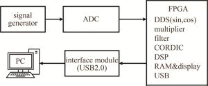
图 12 简化实验验证平台框图
Figure 12. Block diagram of the simplified experimental verification platform

图 13 测振验证平台实物图
Figure 13. Vibration measurement and verification platform
验证过程中,激光波长λ=1565 nm,载波信号s(t)的频率为100 kHz。
$ s(t) = {A_{\rm{c}}}\sin \left( {2\pi {f_{\rm{c}}}t + \frac{{4\pi }}{\lambda }{A_{\rm{v}}}\sin \left( {2\pi {f_{\rm{v}}}t} \right)} \right) $
(10) 式中,Ac为载波幅度;fc为载波频率;Av为目标振幅;fv为目标振动频率。
当目标的振动幅度大于激光波长的1/4时,解调出的相位存在跳变,由(2)式可知,当n增加1时,目标振动幅度发生λ/2的变化。在实验时,设置目标振动信息如表 1所示。
表 1 目标振动幅度与频率(Nc < 10)
Table 1. Amplitude and frequency of target vibration(Nc < 10)
Nc maximum detectable amplitude/nm vibration amplitude Av/nm vibration frequency fv/kHz amplitude φa(i)/(°) 1 1173.750 450 10 207.029 2 1956.250 1300 10 598.083 3 2738.750 2300 4 1058.147 4 3521.250 3000 4 1380.192 5 4303.750 3900 2 1794.249 6 5086.250 4600 2 2116.294 传统相位解缠算法在相位解缠时,需已知相位跳变周期数,在已知跳变周期数的情况下,实现相位解缠。设计传统算法解决跳变周期数为6次以内,按表 1设计目标振动,其补偿结果如图 14所示。

图 14 传统算法多次相位跳变补偿实验结果(Nc < 10)(PC端)
Figure 14. Experimental results of multiple phase jump compensation of traditional algorithm (Nc < 10)(PC)
采用本自动相位解缠算法,其解缠结果如图 15所示。

图 15 自动解缠算法多次相位跳变补偿实验结果(Nc < 10)(PC端)
Figure 15. Experimental results of multiple phase jump compensation for automatic unwinding algorithm (Nc < 10)(PC)
经相位解缠后的解调相位值及其测量误差,如表 2所示。
表 2 解调相位值及其误差(Nc < 10)
Table 2. Demodulation phase and its error (Nc < 10)
Nc phase unwinding algorithm true value of phase amplitude/(°) the measured value φa(i)/(°) absolute error of phase measurement/(°) relative error of phase measurement 1 this algorithm 207.029 207.029 4.267×10⁻⁵ 2.061×10⁻⁷ traditional algorithm 206.943 -0.086 4.135×10⁻⁴ 2 this algorithm 598.083 598.342 0.259 4.326×10⁻⁴ traditional algorithm 598.356 0.273 4.564×10⁻⁴ 3 this algorithm 1058.147 1058.146 -0.001 -8.710×10⁻⁷ traditional algorithm 1058.098 -0.049 -4.622×10⁻⁵ 4 this algorithm 1380.192 1379.834 -0.358 -2.591×10⁻⁴ traditional algorithm 1379.722 -0.469 -3.404×10⁻⁴ 5 this algorithm 1794.249 1794.249 -4.477×10⁻⁴ -2.495×10⁻⁷ traditional algorithm 1794.152 -0.097 -5.415×10⁻⁵ 6 this algorithm 2116.294 2116.127 -0.167 -7.898×10⁻⁵ traditional algorithm 2116.231 -0.063 -2.966×10⁻⁵ 由表 2可知,自动相位解缠算法与传统算法在相位解调精度上基本一致。但传统算法需已知相位跳变周期数,并由跳变周期数选择不同的解缠模块。多轮次的相位补偿,使得其实现繁琐复杂。传统算法与自动相位解缠算法的实现如图 16所示。

图 16 相位解缠算法实现
Figure 16. Implementation of phase unwinding algorithm
由图 16可知,传统相位解缠需根据跳变周期数调用相应的解缠模块,其实现结构复杂,跳变周期数过多或者未知的情况下不再适用。而自动相位解缠算法能自动获取跳变次数,实现相位的自动解缠,结构简洁,且能适应跳变次数较多的情形。
由于传统算法在相位解缠时,随着跳变周期数的增加,在相位补偿后数据位数增加,需设置不同存储器用以数据存储。其中自动解缠算法与传统算法解决6次以内的跳变时,片内存储资源Block RAM中RAMB16BWERs的占用率相较于本相位解缠算法增加了31%,当设计更多次相位跳变解缠模块时,由于资源有限,该解缠算法便难以实现。而自动相位解缠算法其资源使用情况不会因跳变周期数的增加而增大。
为验证当跳变周期数超过10次时,该自动解缠算法的有效性,设置跳变周期数及目标振动的振幅、频率如表 3所示。
表 3 目标振动幅度与频率(Nc>10)
Table 3. Amplitude and frequency of target vibration (Nc>10)
Nc maximum detectable amplitude/nm vibration amplitude Av/nm vibration frequency fv/Hz amplitude φa(i)/(°) 10 8216.250 8000 500 3680.511 20 16041.250 15800 500 7269.010 30 23866.250 23500 500 10811.502 60 47341.250 47000 200 21623.003 90 70816.250 70500 100 32434.505 120 94291.250 94000 100 43246.006 当跳变周期数大于10次时,其补偿效果如图 17所示。其解调相位值及测量误差如表 4所示。

图 17 多次相位跳变补偿实验结果(Nc>10)(PC端)
Figure 17. Experimental results of multiple phase jumps compensation (Nc>10)(PC)
表 4 解调相位值及其误差(Nc>10)
Table 4. Demodulation phase and its error (Nc>10)
Nc true value of phase amplitude/(°) the measured value φa(i)/(°) absolute error of phase measurement/(°) relative error of phase measurement 10 3680.511 3680.436 0.075 2.038×10⁻⁵ 20 7269.010 7268.945 0.065 8.942×10⁻⁶ 30 10811.502 10811.267 0.235 2.174×10⁻⁵ 60 21623.003 21623.061 -0.058 -2.174×10⁻⁶ 90 32434.505 32434.295 0.210 6.475×10⁻⁶ 120 43246.006 43245.753 0.253 5.850×10⁻⁶ 由实验验证结果图 15和图 17可知,该自动相位解缠方法,能有效解决振幅增大导致的解调相位跳变问题,同时由表 2和表 4可知,解调后相位误差在1‰以内。本实验中跳变周期数计数位宽为8 bit,经实验验证能够适用256次以下跳变情况。基于该补偿原理,增加跳变次数计数位宽,本解缠算法在FPGA内能够适应更多次相位跳变情况,且几乎不会耗费更多资源,凸显了该解缠算法的优势。传统相位解缠算法与自动相位解缠算法在设计实现复杂度、资源占用、解决跳变周期数等方面的对比如表 5所示。
表 5 相位解缠算法对比
Table 5. Comparison of phase unwinding algorithms
traditional phase unwinding algorithm automatic phase unwinding algorithm phase unwinding accuracy within 1‰ within 1‰ number of phase jump cycles need to be known no need to know, automatic acquisition degree of design complexity complicated structure simple structure solve the number of jump cycles fewer jumps more jumps (determined by bit width of jumps count) jump 6 times RAM RAMB16BWERs resource occupancy 62% 31% the number of jump cycles increases the usage of RAM RAMB16BWERs resources when the value is greater than 100%, unwinding cannot be achieved keep 31% unchanged -
针对激光多普勒相干测振中,目标振动幅度增大导致解调相位跳变的情况,提出了一种自动相位解缠算法,在FPGA内根据CORDIC输出数据,判断相邻数据信号的非连续性自动寻求跳变周期数,并依次对解调相位进行补偿,实现解调相位的连续输出。相对于传统解缠算法,本算法有效提高了目标振动幅度的测量范围和测量实时性,同时能有效节省FPGA资源。
一种激光多普勒测振相位解缠算法及FPGA实现
A phase unwrapping algorithm for laser Doppler vibration measurement and its FPGA implementation
-
摘要: 为了解决周期性跳变引起的相位解调问题,提出了一种基于现场可编程门阵列(FPGA)的自动相位解缠算法。采用数据流水线结构,通过状态机自动寻求跳变周期数,由跳变周期数实现自动相位补偿,并对提出的算法进行了理论分析和实验验证。结果表明, 在FPGA内设置跳变周期数计数位宽为8位,能适用256次以下跳变情况;当增加跳变周期数计数位宽,可适应更多跳变次数的情况;自动相位解缠算法几乎不占用存储资源;能解决因振动调制范围增大引起的反正切相位跳变问题;相位解调误差在1‰以内,满足高精度振动检测实时性需求。此自动相位解缠算法为激光多普勒振动测量时反正切相位计算结果存在周期性跳变问题提供了更为简洁的解决方案。Abstract: In order to solve the phase demodulation problem caused by cyclic jump, an automatic phase unwrapping algorithm based on field-programmable gate array (FPGA) was proposed. Using the data pipeline structure, the number of jump cycles was automatically found by the state machine, and the automatic phase compensation was realized by the number of jump cycles. The proposed algorithm was theoretically analyzed and verified by experiments. The results show that when the width of the counting bit of the jump cycle number is 8 bits, the FPGA can be applicable to the situation of less than 256 jumps. When the digital width of the jump cycle number increases, more jumps are applicable. The automatic phase unwrapping algorithm almost does not occupy storage resources, and can solve the arctangent phase jump problem caused by the increase of the vibration modulation range. The phase demodulation error is within 1‰, which meets the real-time requirements of high-precision vibration detection. The automatic phase unwrapping algorithm provides a more concise solution to the problem of cyclic jump in the calculation results of arctangent phase in laser Doppler vibration measurement.
-
图 6 φ(i)-φ(i-1) < -π状态时补偿示意图
Figure 6. Schematic diagram of compensation when φ(i)-φ(i-1) < -π state
图 7 φ(i)-φ(i-1)>π状态时补偿示意图
Figure 7. Schematic diagram of compensation when φ(i)-φ(i-1)>π state
图 9 相位解缠算法状态转换示意图
Figure 9. Schematic diagram of state transition of phase unwinding algorithm
图 11 激光多普勒测振及信号处理框图
Figure 11. Block diagram of laser Doppler vibration measurement and signal processing
图 12 简化实验验证平台框图
Figure 12. Block diagram of the simplified experimental verification platform
图 14 传统算法多次相位跳变补偿实验结果(Nc < 10)(PC端)
Figure 14. Experimental results of multiple phase jump compensation of traditional algorithm (Nc < 10)(PC)
图 15 自动解缠算法多次相位跳变补偿实验结果(Nc < 10)(PC端)
Figure 15. Experimental results of multiple phase jump compensation for automatic unwinding algorithm (Nc < 10)(PC)
图 16 相位解缠算法实现
a—传统算法实现 b—自动解缠实现
Figure 16. Implementation of phase unwinding algorithm
a—implementation of traditional algorithm b—implementation of automatic unwinding
图 17 多次相位跳变补偿实验结果(Nc>10)(PC端)
Figure 17. Experimental results of multiple phase jumps compensation (Nc>10)(PC)
表 1 目标振动幅度与频率(Nc < 10)
Table 1. Amplitude and frequency of target vibration(Nc < 10)
Nc maximum detectable amplitude/nm vibration amplitude Av/nm vibration frequency fv/kHz amplitude φa(i)/(°) 1 1173.750 450 10 207.029 2 1956.250 1300 10 598.083 3 2738.750 2300 4 1058.147 4 3521.250 3000 4 1380.192 5 4303.750 3900 2 1794.249 6 5086.250 4600 2 2116.294  下载: 导出CSV
表 2 解调相位值及其误差(Nc < 10)
Table 2. Demodulation phase and its error (Nc < 10)
Nc phase unwinding algorithm true value of phase amplitude/(°) the measured value φa(i)/(°) absolute error of phase measurement/(°) relative error of phase measurement 1 this algorithm 207.029 207.029 4.267×10⁻⁵ 2.061×10⁻⁷ traditional algorithm 206.943 -0.086 4.135×10⁻⁴ 2 this algorithm 598.083 598.342 0.259 4.326×10⁻⁴ traditional algorithm 598.356 0.273 4.564×10⁻⁴ 3 this algorithm 1058.147 1058.146 -0.001 -8.710×10⁻⁷ traditional algorithm 1058.098 -0.049 -4.622×10⁻⁵ 4 this algorithm 1380.192 1379.834 -0.358 -2.591×10⁻⁴ traditional algorithm 1379.722 -0.469 -3.404×10⁻⁴ 5 this algorithm 1794.249 1794.249 -4.477×10⁻⁴ -2.495×10⁻⁷ traditional algorithm 1794.152 -0.097 -5.415×10⁻⁵ 6 this algorithm 2116.294 2116.127 -0.167 -7.898×10⁻⁵ traditional algorithm 2116.231 -0.063 -2.966×10⁻⁵
下载: 导出CSV
表 3 目标振动幅度与频率(Nc>10)
Table 3. Amplitude and frequency of target vibration (Nc>10)
Nc maximum detectable amplitude/nm vibration amplitude Av/nm vibration frequency fv/Hz amplitude φa(i)/(°) 10 8216.250 8000 500 3680.511 20 16041.250 15800 500 7269.010 30 23866.250 23500 500 10811.502 60 47341.250 47000 200 21623.003 90 70816.250 70500 100 32434.505 120 94291.250 94000 100 43246.006
下载: 导出CSV
表 4 解调相位值及其误差(Nc>10)
Table 4. Demodulation phase and its error (Nc>10)
Nc true value of phase amplitude/(°) the measured value φa(i)/(°) absolute error of phase measurement/(°) relative error of phase measurement 10 3680.511 3680.436 0.075 2.038×10⁻⁵ 20 7269.010 7268.945 0.065 8.942×10⁻⁶ 30 10811.502 10811.267 0.235 2.174×10⁻⁵ 60 21623.003 21623.061 -0.058 -2.174×10⁻⁶ 90 32434.505 32434.295 0.210 6.475×10⁻⁶ 120 43246.006 43245.753 0.253 5.850×10⁻⁶
下载: 导出CSV
表 5 相位解缠算法对比
Table 5. Comparison of phase unwinding algorithms
traditional phase unwinding algorithm automatic phase unwinding algorithm phase unwinding accuracy within 1‰ within 1‰ number of phase jump cycles need to be known no need to know, automatic acquisition degree of design complexity complicated structure simple structure solve the number of jump cycles fewer jumps more jumps (determined by bit width of jumps count) jump 6 times RAM RAMB16BWERs resource occupancy 62% 31% the number of jump cycles increases the usage of RAM RAMB16BWERs resources when the value is greater than 100%, unwinding cannot be achieved keep 31% unchanged
下载: 导出CSV
-
[1] SHANG J H, ZHAO Sh G, HE Y, et al. Experimental study on minimum resolvable velocity for heterodyne laser Doppler vibrometry[J]. Chinese Optics Letters, 2011, 9(8): 31-33. [2] JACKSON D A, GARCIA-SOUTO J A, POSADA-ROMAN J E. Ca-libration of laser Doppler vibrometer exploiting Bessel functions of the first kind[J]. Electronics Letters, 2015, 51(14): 1100-1102. doi: 10.1049/el.2015.0972 [3] NOZATO H, KOKUYAMA W, SHIMODA T, et al. Calibration of laser Doppler vibrometer and laser interferometers in high-frequency regions using electro-optical modulator[J]. Precision Engineering, 2021, 70: 135-144. doi: 10.1016/j.precisioneng.2021.01.016 [4] 王凯旋, 武俊峰, 舒风风. 压电陶瓷频率响应及振动面幅值激光外差测量[J]. 压电与声光, 2021, 43(5): 680-683. WANG K X, WU J F, SHU F F. Laser heterodyne measurement of frequency response and amplitude of vibrating surface of piezoelectric ceramics[J]. Piezoelectrics and Acoustooptics, 2021, 43(5): 680-683(in Chinese). [5] HE G T, WANG X Zh, ZENG A J, et al. Real-time displacement measurement with large range and high accuracy using sinusoidal phase modulating laser diode interferometer[J]. Chinese Optics Le-tters, 2007, 5(4): 211-214. [6] 杨明, 蔡晨光, 王颖, 等. 外差式激光干涉信号的采集与解调方法综述[J]. 激光杂志, 2018, 39(1): 20-24. YANG M, GAI Ch G, WANG Y, et al. Review of acquisition and demodulation method of heterodyne interferometer signal[J]. Laser Journal, 2018, 39(1): 20-24(in Chinese). [7] 陈鸿凯. 激光多普勒微振动信号处理技术研究及硬件实现[D]. 长春: 中国科学院大学(中国科学院长春光学精密机械与物理研究所), 2020: 7-36. CHEN H K. Research on signal processing and hardware implementation of laser Doppler micro vibration[D]. Changchun: University of Chinese Academy of Sciences (Changchun Institute of Optics, Fine Mechanics and Physics, Chinese Academy of Sciences), 2020: 7-36(in Chinese). [8] BAUER M, RITTER F, SIEGMUND G. High-precision laser vibro-meters based on digital Doppler signal processing[J]. Proceedings of the SPIE, 2002, 4827: 50-61. doi: 10.1117/12.468166 [9] 张建斌, 梁芳, 刘乃安. 一种改进型CORDIC算法的FPGA实现[J]. 微电子学与计算机, 2010, 27(11): 181-184. ZHANG J B, LIANG F, LIU N A. FPGA implement of a modified CORDIC algorithm[J]. Microelectronics & Computer, 2010, 27(11): 181-184(in Chinese). [10] 刘礼刚, 曾延安, 常大定. 基于FPGA的反正切函数的优化算法[J]. 微计算机信息, 2007, 23(17): 203-204. LIU L G, ZENG Y A, GHANG D D. The design and optimization of arctangent calculate circuit based on FPGA[J]. Microcomputer Information, 2007, 23(17): 203-204(in Chinese). [11] 刘小会, 许蕾, 刘海颖, 等. 基于CORDIC改进算法的反正切函数在FPGA中的实现[J]. 计算机技术与发展, 2013, 23(11): 103-107. LIU X H, XU L, LIU H Y, et al. Realization of arctangent function based on improved CORDIC algorithm in FPGA[J]. Computer Technology and Development, 2013, 23(11): 103-107(in Chin-ese). [12] MARTENS V, HANS J. Invited article: Expanded and improved traceability of vibration measurements by laser interferometry[J]. Review of Scientific Instruments, 2013, 84(12): 121601. [13] WANG L W, ZHANG M, MAO X H, et al. The arctangent a-pproach of digital PGC demodulation for optic interferometric sensors[J]. Proceedings of the SPIE, 2006, 6292: 62921E. [14] WANG G Q, XU T W, FANG L. PGC demodulation technique with high stability and low harmonic distortion[J]. IEEE Photonics Technology Letters, 2012, 24(23): 2093-2096. [15] LIANG Y R, DUAN H Z, YEH H C, et al. Fundamental limits on the digital phase measurement method based on cross-correlation analysis[J]. Review of Scientific Instruments, 2012, 83(9): 095110. [16] KOWARSCH R, TE R, RMEBR C. Laser-Doppler vibrometer microscope with variable heterodyne carrier[J]. Journal of Physics Conference Series, 2018, 1149(1): 12016. [17] GUTIERREZ R, VALLS J. Implementation on FPGA of a LUT-based atan(Y/X) operator suitable for synchronization algorithms[C]//2007 International Conference on Field Programmable Logic and Applications. Amsterdam, Netherlands: IEEE, 2007: 472-475. [18] 鲍宜鹏. 一种CORDIC算法优化及32位浮点反正切函数FPGA实现[J]. 电子与封装, 2015, 15(3): 22-25. BAO Y P. One improved CORDIC algorithm of calculating 32 bit floating the arctangent functions with FPGA[J]. Electronics and Packaging, 2015, 15(3): 22-25(in Chinese). [19] 骆艳卜, 张会生, 张斌, 等. 一种CORDIC算法的FPGA实现[J]. 计算机仿真, 2009, 26(9): 305-307. LUO Y B, ZHANG H Sh, ZHANG B, et al. FPGA implementation of a CORDIC algorithm[J]. Computer Simulation, 2009, 26(9): 305-307(in Chinese). [20] TRIBPLET J M, MEMBER S. A new phase unwrapping algorithm[J]. IEEE Transactions on Acoustics, Speech, and Signal Processing, 1977, 25(2): 170-177. [21] REN Y X, DANG A H, LIU L, et al. Heterodyne efficiency of a coherent free-space optical communication model through atmospheric turbulence[J]. Applied Optics, 2012, 51(30): 7246-7254. [22] CHOI H, PARK K, LA J. Novel phase measurement technique of the heterodyne laser interferometer[J]. Review of Scientific Instruments, 2005, 76(9): 93105. -

 点击查看大图

计量
- 文章访问数: 1265
- HTML全文浏览量: 801
- PDF下载量: 19
- 被引次数: 0
