Advanced Search

ISSN1001-3806 CN51-1125/TN Map

Volume 43 Issue 2
Jan.  2019
Article Contents
Turn off MathJax

Citation:

Research of positioning technology of Mach-Zehnder interferometer

  • Corresponding author: KONG Yong, kkyy7757@aliyun.com
  • Received Date: 2018-05-03
    Accepted Date: 2018-05-30
  • In order to study effect of laser sources with different linewidthes on positioning accuracy of Mach-Zehnder fiber interferometers, a set of disturbance location system was built using the principle of mutual-correlation positioning algorithm.3kHz and 1MHz semiconductor lasers were used as system output light sources respectively, and were subjected to multiple fixed-point disturbances.The experimental data were calculated according to the principle of mutual correlation, and the results were compared and analyzed.The results show that, in the case of time domain sampling rate of 100MHz, average positioning error of 3kHz laser is 34.4m, far less than positioning error of 225.4m for 1MHz light source.The method of using 3m single-mode fiber in the signal arm of the interferometer to make the signal arm and the reference arm basically the same length, largely suppresses the common-mode noise of the system.Narrow linewidth laser can improve the positioning accuracy of the system.The study has positive significance for the selection of interferometer lasers and the evaluation of system performance parameters.
  • 加载中
  • [1]

    ZOU D B, LIU H, ZHAO L, et al. Research of signal recognition of distributed optical fiber vibration sensors[J]. Laser Technology, 2016, 40(1):86-89(in Chinese).
    [2]

    XIE Sh R, ZOU Q L, TU Y J, et al. A study on real-time location method for long distance dual M-Z interferometric vibration sensor[J]. Journal of Optoelectronics·Laser, 2009, 20(8):1020-1024(in Chinese).
    [3]

    LIU B, YANG Y F, ZHANG J, et al. A fiber fence system based on M-Z interferometer[J]. Acta Photonica Sinica, 2007, 36(6):1013-1017(in Chinese).
    [4]

    CHEN W M, WU J, TAN J, et al. Locating technology for twin Mach-Zehnder distributed optical fiber sensing system[J].Acta Optica Sinica, 2007, 27(12):2128-2132(in Chinese).
    [5]

    ZHANG Y, CHEN J M, LI G, et al. Locatin method of distributed fiber-optic perimeter security system based on Mach-Zehnder interfe-rometer[J]. Chinese Journal of Lasers, 2012, 39(6):605005(in Chinese).
    [6]

    YANG Sh Zh, ZHANG Zh Y, SHAO L Y, et al. A quadratic correlation method for vibration localization based on dual M-Z fiber sensor[J]. Acta Photonica Sinica, 2017, 46(7):706004(in Chinese).
    [7]

    CHEN Q N, LIU T G, LIU K, et al. A positioning algorithm based on super-resolution time delay estimation in dual Mach-Zehnder interferometry disturbance sensor[J].Proceedings of the SPIE, 2014, 9274:92740U.
    [8]

    LIN W T, LOU Sh Q, LIANG Sh. A modified phase generation carrier technique for fiber-optic distributed disturbance sensor[J]. Optik-International Journal for Light and Electron Optics, 2014, 125(3):942-945.
    [9]

    SUN Q Zh, LIU D M, WANG J, et al. Distributed fiber-optic vibration sensor using a ring Mach-Zehnder interferometer[J]. Optics Communications, 2008, 281(6):1538-1544.
    [10]

    CHEN Q N, LIU T G, LIU K, et al. An Improved positioning algorithm with high precision for dual Mach-Zehnder interferometry disturbance sensing system[J]. Journal of Lightwave Technology, 2015, 33(10):1954-1960.
    [11]

    AN Y, FENG H, ZHOU Y, et al. A control method to eliminate polarization-induced Phase distortion in dual Mach-Zehnder fiber interferometer[C]//Ukacc International Conference on Control. New York, USA: IEEE, 2012: 988-991.
    [12]

    CHEN Q N, LIU T G, LIU K, et al. An elimination method of polarization-induced phase shift and fading in dual Mach-Zehnder interferometry disturbance sensing system[J]. Journal of Lightwave Technology, 2013, 31(19):3135-3141.
    [13]

    JIANG J Sh, JIANG Y, LIU D, et al. Fiber-optic perimeter security system based on dual Mach-Zehnder interferometer structure[J]. Optical Technique, 2015, 41(3):193-196(in Chinese).
    [14]

    JIN J, LIANG D K, ZENG J, et al. Study on distributed fiber-optic detecting system based on Mach-Zehnder interferometer[J]. Optoelectronic Technology, 2013, 33(3):160-163(in Chinese).
    [15]

    WANG M Y, SHENG L, TAO Y, et al. Effect of laser linewidth on characteristics of ϕ-OTDR system[J]. Laser Technology, 2016, 40(4):615-618(in Chinese).
    [16]

    SHI Y L, ZHANG Y, SUN L J. Influence of lasers on phase noise of optoelectronic oscillators[J]. Laser Technology, 2015, 39(6):761-764(in Chinese).
    [17]

    CHEN Q N. Research on key technologies of dual Mach-Zehnder distributed vibration sensing system[D]. Tianjin: Tianjin University, 2015: 23-26(in Chinese).
    [18]

    JIN J. Research of distributed fiber optic cable detection system based on the structure of Mach-Zehnder[D].Nanjing: Nanjing University of Aeronautics and Astronautics, 2013: 29-32(in Chinese).
    [19]

    LIU F, XIE SH R, QIU X K, et al. Efficient common-mode noise suppression for fiber-optic interferometric sensor using heterodyne demodulation[J]. Journal of Lightwave Technology, 2016, 34(23):5453-5461.
    [20]

    LI R, LIANG Sh, XIAO W. A low cost design to eliminate polarization induced phase shift for dual Mach-Zehnder fiber interferometer[J]. Proceedings of the SPIE, 2015, 9656:965609.
    [21]

    HUANG W W. Research on polarization control technology in distributed optical fiber fence protection system[D]. Chengdu: Southwest Jiaotong University Master Degree Thesis, 2016: 16-17(in Ch-inese).
    [22]

    CHEN X G. A new type of fiber-optic interferometer with high sensitivity and common mode compensation[J]. Acta Photonica Sinica, 1992, 12(2):188-192(in Chinese).
  • 加载中
通讯作者: 陈斌, bchen63@163.com
  • 1. 

    沈阳化工大学材料科学与工程学院 沈阳 110142

  1. 本站搜索
  2. 百度学术搜索
  3. 万方数据库搜索
  4. CNKI搜索

Figures(7) / Tables(3)

Article views(4847) PDF downloads(85) Cited by()

Proportional views

Research of positioning technology of Mach-Zehnder interferometer

    Corresponding author: KONG Yong, kkyy7757@aliyun.com
  • 1. College of Electrical and Electronic Engineering, Shanghai University of Engineering Science, Shanghai 201620, China
  • 2. Shanghai HuaCe Navigation Technology Ltd., Shanghai 201702, China

Abstract: In order to study effect of laser sources with different linewidthes on positioning accuracy of Mach-Zehnder fiber interferometers, a set of disturbance location system was built using the principle of mutual-correlation positioning algorithm.3kHz and 1MHz semiconductor lasers were used as system output light sources respectively, and were subjected to multiple fixed-point disturbances.The experimental data were calculated according to the principle of mutual correlation, and the results were compared and analyzed.The results show that, in the case of time domain sampling rate of 100MHz, average positioning error of 3kHz laser is 34.4m, far less than positioning error of 225.4m for 1MHz light source.The method of using 3m single-mode fiber in the signal arm of the interferometer to make the signal arm and the reference arm basically the same length, largely suppresses the common-mode noise of the system.Narrow linewidth laser can improve the positioning accuracy of the system.The study has positive significance for the selection of interferometer lasers and the evaluation of system performance parameters.

引言
  • 相比传统的电传感器,分布式光纤传感系统应用场景较为灵活,可在空间狭窄、易燃易爆易腐蚀等恶劣场景中工作,不仅成本低,而且整个光纤传感链路都能对外部信号进行感知[1],所以被国内外科研工作者视为研究的热点。其中,马赫-曾德尔作为干涉型的分布式光纤传感系统,由于具有很高的灵敏度,并能准确地实时定位外界扰动,因而在周界防护系统中有着较大的优势。但是,系统光源的噪声、光纤双折射引起的偏振噪声、外界环境引起的相位噪声等都会对马赫-曾德尔干涉仪的定位精度带来影响。此外,干涉仪的测量范围也受到各种因素的影响。一方面,当干涉仪的信号臂某处发生振动的同时,干涉臂沿线各个位置也会发生十分微弱的振动,这些微弱振动累计后会影响系统输出的干涉信号,且传感的距离越长,累计的微弱振动对系统的影响越明显,就会导致顺时针和逆时针方向的时间差Δt出现的误差越大,进而影响定位结果;另一方面,当干涉仪的传感范围很长时(几十甚至上百公里),干涉仪的信号臂与参考臂的长度很难精确控制,不可避免地会形成臂长差,而臂长差会导致系统共模噪声以及其它噪声的影响,此时干涉信号的信噪比和可见度会大大降低,影响定位结果。另外,当干涉仪的传感范围很大时,光纤沿线形成的总的散射噪声也很大,这也会对定位精度产生不利影响[2]

    目前,系统的传感距离和定位精度在一定程度上得到了很大的提升[3-5],但是定位误差还有较大的提升空间。为了提高定位精度,CHEN和YANG等人分别先后将两路输出的相干信号,做二次相关运算提高系统的信噪比[6-7]。一些研究人员通过将改进信号解调方法,补偿传感光纤的时延去提高系统信噪比,改善初始相位误差带来的定位误差[8]。一些研究人员从系统的光路结构[9]和激光源的频率噪声[10]入手去分析系统的定位性能。此外,系统的偏振态分析也是影响定位性能的重要因素[11-12]

    虽然系统的定位精度和传感距离都有了很大的提高,但是影响系统性能的其它因素还有待分析。为了研究激光器线宽和系统共模噪声对系统定位进度和稳定性能的影响,作者分别把线宽为3kHz和1MHz半导体激光光源应用到马赫-曾德尔系统中,使用互相关算法进行定位,证明了窄线宽激光器可以提高系统的定位精度;同时,在信号臂中接入3m单模光纤,成功地抑制了系统的共模噪声,提高系统的稳定性。

1.   理论分析
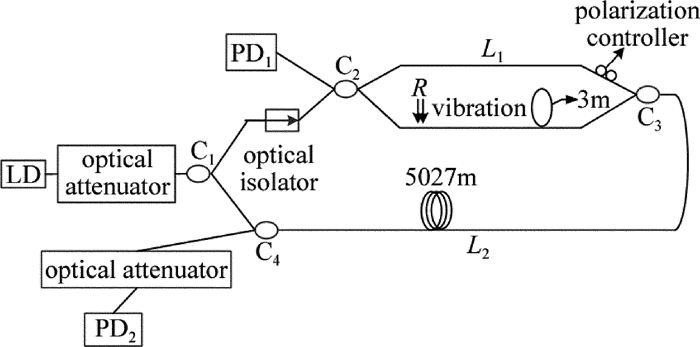
  • 马赫-曾德尔干涉仪(Mach-Zehnder interferometer, MZI)的系统结构图如图 1所示。其包括两种不同线宽的激光源(3kHz/1MHz)、两个可调光衰减器、耦合器C1, C2, C3, C4、光电探测器PD1和PD2、5.027km的单模光纤和手动偏振控制器。可调光衰减器的作用是调节光源的输出功率使其和传感模块输入的光功率匹配。光隔离器的作用是防止后向散射光对光路产生不利影响。激光光源光源发出的连续光被调制后变成脉冲光,首先经过光衰减器,被耦合器C1分成两束相同的光源,分别沿着顺、逆时针方向传播。顺时针方向的光经过MZI结构在C3处发生干涉,经过传感光纤和耦合器C4被光电探测器PD2接收;同理,逆时针方向的光束先经过传感光纤进入MZI系统后在C2处发生干涉并被PD1接收。当外界没有振动时,光电探测器显示的干涉信号较为稳定。

    Figure 1.  Structure of double Mach-Zehnder interferometer system

    当MZI系统上的某一点距耦合器C2R处产生扰动时,MZI中的顺时针和逆时针方向传播的光相位同时变化,若顺时针方向的信号到达PD2时间为t1,逆时针方向的信号到达PD1时间为t2[13],则t1=(L1+L2-R)/vt2=R/v,则:

    式中,光在光纤中的传播速率v=c/nc=3×108m/s为真空光速,n为光纤的纤芯折射率,L1表示耦合器C2与耦合器C3的距离,L2表示耦合器C3与耦合器C4的距离,Δt表示光电探测器的时间差。将v带入,并对上式进行变换,得到:

    因此,知道时间差Δt,就可计算出R的大小,扰动的位置则可以精确定位。使用互相关算法求Δt。两光电探测器的输出可分别表示为:y1(t)=s(t)+n1(t),y2(t)=s(tt)+n2(t)。其中,s(t)和s(tt)为振动产生的扰动信号,n1(t)和n2(t)为白噪声,白噪声相互独立,且与扰动信号互不相关,则两个信号的互相关函数为:

    式中,T为两路信号做互相关时的周期;τ表示两路信号做相关之后,互相关函数R(τ)的自变量;Rs(τt)为y1(t)与y2(τt)之间的互相关函数。

    由分析可知,当τt时取最大值。将其离散化,则两信号的互相关函数为[14]

    式中,L为采样长度,lm为整数,Ts为采样周期。所以,只要测得有限长的互相关序列R12(mTs)中的最大值对应的序列号m,即可求出扰动位置,完成定位。

  • 光源的线宽是影响系统定位精度的重要参量,激光器通常具有一定的带宽[15],因为激光器光谱中包含多个谱分量,且谱线宽度与光谱纯度、相干性密切相关[16],因而,光源线宽的特性决定了光源的相干长度。为了使MZI的光波能干涉,干涉仪信号臂和参考臂的臂长差要小于激光光源的相干长度,即满足λ2λL,其中, λ为光源的中心波长,Δλ是臂长差,ΔL为两臂长差,并且激光器输出的光源具有一定的谱宽。假设功率谱为I0(k)的窄线宽光源入射到MZI后,输出可表示为:

    式中,k为波数,Δξ为两臂光程差。若光源的中心波长为k0,并令x=k-k0j(x)=I(k0+x),则上式化为:

    展开后为:

    式中,

    分析(7)式可知,当臂长差为定值时,激光光源线宽越窄,干涉仪输出信号的可见度就越大,信号质量就越好。所以干涉应尽可能使用窄线宽的激光光源[17]。另外,当激光源的线宽变窄时,相应的,频率漂移也更小,相位噪声变小,强度噪声也随之减小,故而信号信噪比变大,定位误差更小。需要注意的是, 光源线宽不可能无限减小,一方面是由于制作工艺和制作成本的限制,另一方面是随着线宽的减小,线宽对信号可见度的影响也越来越小,所以实际应用时应综合考虑。

2.   数值仿真
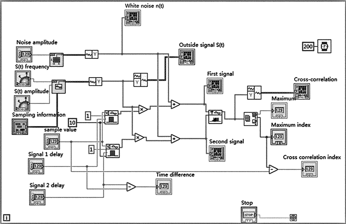
  • 在LabView中通过仿真两路相关信号,并对其做互相关运算模拟定位仿真的具体过程。仿真的程序框图如图 2所示。为了仿真现实中的扰动信号,引入高频余弦信号和矩形脉冲信号控件,将两信号做乘法运算得到高频余弦脉冲信号。考虑到现实环境中噪声不可避免,再将得到的信号加上均匀的白噪声,得到传输信号与噪声信号的混合。将两路仿真混合信号用互相关控件进行互相关的运算,输出结果的波形由一个波形显示控件进行显示。再将数组最大值和最小值控件与之相连,以此获得对应的时间点,计算两路相干信号的时间差[18]

    Figure 2.  Block diagram of cross-correlation positioning simulation

    前面板设计图如图 3所示。噪声幅值设置为0.01,第1路信号和第2路信号的时间延迟分别为120ms和150ms,采样值设置为20000,外界信号的频率和幅值可根据需要转动旋转按钮,外界信号的采样信息也设定好,定位的结果如图 3所示。

    Figure 3.  Front panel of cross-correlation positioning simulation

    互相关波形的最大值索引在1031处,仿真结果表明,基于MZI的互相关算法理论上能对扰动的位置进行精确的定位。

    下面通过实际系统光路的搭建对扰动位置进行探测,并通过数学计算定位扰动的位置。

3.   实验设计与结果分析
  • 实验结构按图 1所示进行搭建。为了区分出两光电探测器的信号,采用4.980km的传感光纤,各光学器件之间的连接光纤较短,总长度为几十厘米,对定位误差影响很小,传输的时间也可忽略不计。干涉仪中偏振控制器的长度为3m,实验中所采用的1×2, 2×2耦合器的功率损耗分别为2dB和3dB,单模光纤的中心波长为1550nm,纤芯折射率为1.5,在MZI信号臂进行扰动,采集卡的采样频率为100MHz的调节偏振控制器,使得两路信号的偏振特性较为一致。当激光光源采用3kHz的窄线宽激光器时,定位结果如图 4所示。

    Figure 4.  System positioning using 3kHz laser source

    图 4的第1行两个波形从左到右分别是做互相关运算截取的两路信号,互相关运算后的信号,第2行的两个波形分别是分开后两路相干信号。当两路信号偏振态较为一致时,干涉仪互相关R12定位的最大值点位于在497527处,此时互相关后信号的最大值点距中点的距离为500000-497527=2473点,由于截取两路信号的时间为0.005s,对应的两路波形图的刻度为500000,根据显示波形计算两路信号定位的时间差为:

    而实际的定位时间差为:

    则定位的时间误差Δt=24.915-24.730=0.185μs,则定位误差$\Delta x = v \times \Delta t = \frac{c}{n} \times \Delta t = \frac{{3 \times {{10}^8}}}{{1.5}} \times 0.185{\rm{ \mathsf{ μ} s}} = 37{\rm{m}}$。为了验证MZI的可靠性,再重复试验9次,共计10次实验,得到的最大点、时间误差和定位误差如表 1所示。

    maximum point 497527 497527 497530 497532 497522 497527 497533 497525 497518 497516
    time error Δt/μs 0.185 0.185 0.215 0.235 0.135 0.185 0.245 0.165 0.095 0.075
    positioning error/m 37 37 43 47 27 37 49 33 19 15

    Table 1.  3kHz laser source positioning

    将10次测量的定位误差取绝对值后平均,得到3kHz时系统的定位误差为34.400m。相同的实验条件,唯一变化的是MZI光源采用1MHz,调节两路信号的偏振态,则定位结果如图 5所示。

    Figure 5.  System positioning using 1MHz laser source

    干涉仪互相关R12定位的最大值点位于497623处,此时最大值点距中点的距离为500000-497623=2377点,则两路信号的定位时间差为:0.005 500000 ×(500000-497623)=23.770μs,定位的时间误差Δt=24.915-23.770=1.145μs,定位误差$\Delta x = v \times \Delta t = \frac{c}{n} \times \Delta t = \frac{{3 \times {{10}^8}}}{{1.5}} \times 1.145{\rm{ \mathsf{ μ} s}} = 229{\rm{m}}$。同理,再重复试验9次,得到的最大值点、时间误差和定位误差如表 2所示。

    maximum point 497623 497622 497623 497623 497619 497632 497615 497611 497627 497617
    time error Δt/μs 1.145 1.135 1.145 1.145 1.105 1.235 1.065 1.025 1.185 1.085
    positioning error/m 229 227 229 229 221 247 213 205 237 217

    Table 2.  1MHz laser source positioning

    将10次定位误差结果取平均值,得到1MHz时系统的定位误差为225.400m。综合两种不同情况下的实验数据,很明显,采用3kHz窄线宽的激光光源,MZI的定位精度较高,定位误差较小。需要特别说明的是,由于条件限制,实验中采集两路相干信号的时间段较短,为0.005s,这会降低互相关定位时的定位精度,若扩大采集信号的时间范围,则两路相干信号整体上呈正弦波形,定位误差也会在一定程度上得到减小。

  • 在MZI中,共模噪声很大程度上降低了干涉仪的信噪比。当MZI两臂长度不等时, 共模噪声对系统有较大的影响。如图 1所示,若信号臂和参考臂的长度相差较大时,激光器顺时针方向的光通过耦合器C2被引导到MZI系统中,被分成两个臂的脉冲,分别具有f1f2的频移值。由于光纤长度差,两个脉冲在时间上分开,并通过耦合器C3组合,产生一对差分延迟脉冲,此时MZI即为补偿干涉仪,也是引入共模噪声的关键部位[19]。共模噪声主要分布在在几十赫兹到几千赫兹的频率范围内。在搭建光路系统的过程中,为了控制系统的偏振态,在干涉仪的参考臂中加入了3m长的偏振控制器[20-21],此时信号臂和参考臂的长度不一致,为了抑制共模噪声减小光源波长波动及环境干扰对系统的影响,要求干涉仪两路完全对称[22]。所以相应的,作者在信号臂中接入3m长的单模光纤。考虑到实验两臂长存在误差,不可能完全相等,故又在参考臂中加入光纤延时器,通过光纤延时器的微调,使得两臂长无限接近,通过对干涉仪两臂的适当调节,使得系统偏振态在较为理想的情况下,通过示波器对比共模噪声抑制前后的波形变化,如图 6a图 6b所示。

    Figure 6.  a—before common mode noise suppression b—after common mode noise suppression

    从图中可以看出,共模抑制前,MZI输出的两路信号波宽“较大”,此时信号的信噪比和可见度较差,对后续的信号处理有很大的影响。而在共模抑制后,系统输出的两路信号十分“锐利”,此时信号具有很高的信噪比,很大程度上改善了振动定位测量。类似的,在线宽为3kHz激光光源的条件下,在干涉仪信号臂相同的位置进行10次扰动,共模抑制前和共模抑制后的定位误差绝对值经计算分别如表 3所示。

    number of disturbances 1 2 3 4 5 6 7 8 9 10
    before common mode
    suppression/m
    74 63 91 61 73 68 61 81 73 69
    after common mode
    suppression/m
    37 37 43 47 27 37 49 33 19 15

    Table 3.  Positioning errors before and after common mode rejection
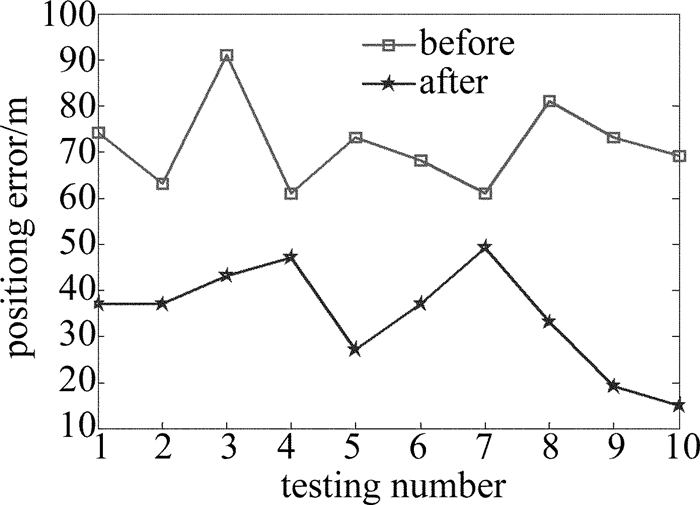
    将以上数据用折线图表示,如图 7所示。

    Figure 7.  Systematic positioning error before and after common mode noise suppression

    图 7清楚地显示了共模噪声抑制前后的定位误差,共模抑制后的定位误差明显要小于共模抑制前的定位误差。这进一步证明了共模噪声降低系统的信噪比,使得系统的定位性能下降,所以应该尽量保证MZI信号臂和参考臂长度的一致,抑制共模噪声对系统的不良影响。

4.   结论
  • 基于互相关定位的MZI在理论推导和光路分析的基础上,证明了采用3kHz窄线宽的激光光源的定位误差远远小于1MHz的情况,最小定位误差达15m,通过实验证明了窄线宽激光光源可以提高MZI的定位精度。为了抑制系统的共模噪声、提高系统的信噪比,通过在信号臂增加3m长的单模光纤使得长度和参考臂的长度接近,很好地改善了系统的定位误差。所搭建的MZI具有良好的定位功能。

Reference (22)

Catalog

    /

    DownLoad:  Full-Size Img  PowerPoint
    Return
    Return