Advanced Search

ISSN1001-3806 CN51-1125/TN Map

Volume 43 Issue 2
Jan.  2019
Article Contents
Turn off MathJax

Citation:

Automatic positioning of optical axis of wave-plate in a laser feedback birefringence measurement system

  • Received Date: 2018-04-17
    Accepted Date: 2018-09-03
  • In order to solve the problem of complex structure, time-consuming and unstable state in the process of adjusting optical elements in a traditional birefringence measurement system, the duty cycles of o light and e light at low levels in polarization flipping curves were calculated.The function of automatic rotating wave-plate was added in a birefringence measurement system optimized with high efficiency.The system can automatically adjust the direction of fast axis of the wave-plate aligned with the intrinsic polarization direction of laser and reduce the measurement error that may be introduced when judging the fast axis of wave-plate artificially.After many measurements, the results show that the maximum deviation of wave-plate phase delay is 0.65°, and the standard deviation is reduced by 28%.The measurement accuracy and stability of birefringence measurement systems have met the requirements of industrial production.
  • 加载中
  • [1]

    FEI L, ZHANG S, LI Y, et al. Polarization control in a He-Ne laser using birefringence feedback[J]. Optics Express, 2005, 13(8):3117-3122.
    [2]

    GUO B, ZHU K, ZHANG S, et al. Single-spot two-dimensional displacement measurement based on self-mixing interferometry[J]. Optica, 2017, 4(7):729-732.
    [3]

    LI H H, ZHANG Sh L, TAN Y D, et al. Wave plate phase retardation measurement on contact block based on optical feedback[J]. Journal of Applied Optics, 2011, 32(5):1004-1008(in Chinese).
    [4]

    CUI L, ZHANG Sh L. Semi-classical theory model for feedback effect of orthogonally polarized dual frequency He-Ne laser[J]. Optics Express, 2005, 13(17):6558-6563.
    [5]

    LIU M, ZHANG Sh L, LIU W X, et al. Error source and its elimination in phase retardation measurement of wave plate based on laser feedback[J]. Journal of Applied Optics, 2008, 29(6):961-966(in Chinese).
    [6]

    TAN Y D, ZHANG Sh L. Orthogonally linearly polarized dual frequency Nd:YAG lasers with tunable frequency difference and its application in precision angle measurement[J]. Chinese Physics Letters, 2007, 24(9):2590-2593.
    [7]

    WU Y, TAN Y D, ZHANG Sh L, et al. Polarization characteristics of He-Ne laser with different directions of polarized feedback[J]. Applied Optics, 2013, 52(22):5371-5375.
    [8]

    WU Y, TAN Y D, ZENG Z, et al. Note:High-performance He-Ne laser feedback interferometer with birefringence feedback cavity scanned by piezoelectric transducer[J]. Review of Scientific Instruments, 2013, 84(5):180-184.
    [9]

    ZENG M, DING J X. Polarization characteristics of external cavity He-Ne lasers[J]. Laser Technology, 1992, 16(1):21-28(in Chinese).
    [10]

    ZENG Z, QU X, TAN Y, et al. High-accuracy self-mixing interferometer based on single high-order orthogonally polarized feedback effects[J]. Optics Express, 2015, 23(13):16977-16983.
    [11]

    WEI Zh M, YANG K Y. Controller of multi-axis motorized optical stages based on DAQ card and multiplexer[J].Laser Journal, 2010, 31(5):38-39(in Chinese).
    [12]

    WANG L, LI G H, KONG Ch, et al. Phase retardation measurement with two λ/4 wave-plates[J]. Laser Technology, 2007, 31(6):663-664(in Chinese).
    [13]

    XU L, ZHANG Sh L, TAN Y D, et al. Simultaneous measurement of refractive-index and thickness for optical materials by laser feedback interferometry[J]. Review of Scientific Instruments, 2014, 85(8):1693-1697.
    [14]

    LIN Y H, QU X Sh, WANG D G, et al. Research on measurement system for phase retardation for wave plates based on auto data acquisition[J]. Measurement & Control Technology, 2010, 29(6):41-44(in Chinese).
    [15]

    WAN L Y, SUN J F, LIU L R, et al. Effects of optical axis deviation of wave-plates on the amplitude and phase of beams separated by a polarizing splitter[J]. Optical Technique, 2010, 36(2):307-310(in Chinese).
    [16]

    ZHANG J, LI G H. The theory of correcting the retardation devation of a wave-plate[J]. Laser Technology, 2006, 30(3):274-276(in Chinese).
    [17]

    SUO G G, WANG X R, HUANG Z Q, et al. Test method for birefaingence of Fourier quarter-wave-plate.Laser Technology, 2016, 40(1):131-135(in Chinese).
    [18]

    GAO A, KONG Y, XIA G, et al. Research of temperature insensitivity of uniaxial birefringence filters[J]. Laser Technology, 2016, 40(4):476-478(in Chinese).
    [19]

    XU C, TAN Y, ZHANG S, et al. The structure measurement of micro-electro-mechanical system devices by the optical feedback tomography technology[J]. Applied Physics Letters, 2013, 102(22):3648-3704.
    [20]

    ZHANG P, TAN Y D, LIU W X, et al. Methods for optical phase retardation measurement:a review[J]. Science China, 2013, 56(5):1155-1164.
  • 加载中
通讯作者: 陈斌, bchen63@163.com
  • 1. 

    沈阳化工大学材料科学与工程学院 沈阳 110142

  1. 本站搜索
  2. 百度学术搜索
  3. 万方数据库搜索
  4. CNKI搜索

Figures(5) / Tables(2)

Article views(6844) PDF downloads(84) Cited by()

Proportional views

Automatic positioning of optical axis of wave-plate in a laser feedback birefringence measurement system

  • School of Mechanical Engineering, Nantong University, Nantong 226019, China

Abstract: In order to solve the problem of complex structure, time-consuming and unstable state in the process of adjusting optical elements in a traditional birefringence measurement system, the duty cycles of o light and e light at low levels in polarization flipping curves were calculated.The function of automatic rotating wave-plate was added in a birefringence measurement system optimized with high efficiency.The system can automatically adjust the direction of fast axis of the wave-plate aligned with the intrinsic polarization direction of laser and reduce the measurement error that may be introduced when judging the fast axis of wave-plate artificially.After many measurements, the results show that the maximum deviation of wave-plate phase delay is 0.65°, and the standard deviation is reduced by 28%.The measurement accuracy and stability of birefringence measurement systems have met the requirements of industrial production.

引言
  • 双折射测量系统基于激光回馈效应[1],即激光器的输出光被外物反射到激光器的内腔,并与激光器内腔中光束相干涉,引起光强发生变化。从传统的激光回馈理论模型中,研究人员得出回馈镜移动半个波长对应光强波动一个周期等结论,这为激光回馈技术在测量速度、形状、角度、位移[2]等领域的应用提供了理论基础。波片作为光学系统中的重要元件,被广泛地应用在通讯技术、医学技术和军事研究等诸多领域,其加工精度及偏振态测量精度需要达到较高的生产标准。但是在实际的波片测量过程中,测量系统容易受到外界温度、光强、振动等因素影响,这将在一定程度上降低波片的测量精度[3]。清华大学CUI等人提出半经典理论和F-P腔模型相结合的理论模型[4],设计出基于激光回馈效应的双折射测量系统, 该系统根据偏振跳变点与其等光强点位置,建立了与双折射元件相位延迟大小的关系式。在使用双折射测量系统前,研究人员必须调节波片,使波片的快轴方向准确地对准激光器本征偏振方向[5],以此达到精确测量波片相位延迟的要求。但是在重复测量过程中作者发现, 研究人员每次都要通过观察偏振态信号判断非偏振片通光方向的光强是否处于最小位置,这使系统的稳定性和重复性存在问题。

    针对这一问题,作者对原有的双折射测量系统进行优化。通过计算渥拉斯顿棱镜分光后o光、e光低电平的占空比,并结合MPC07运动控制卡、电动3维平移台自动调节波片方位,使得波片快轴方向与激光器的本征偏振方向保持一致。从而减小人为旋转波片过程中可能引入的粗大误差和随机误差,降低了测量结果的不确定度。优化后的波片测量系统能得到更加标准的偏振跳变曲线,在一定程度上提高了测量效率和测量精度。

1.   实验
  • 在偏振跳变的理论基础上[6],双折射测量系统出现如图 1所示的偏振跳变现象。

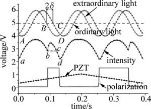
    Figure 1.  Graph of polarization flipping

    图中,PZT为压电陶瓷(piezoelectric ceramic)。o光和e光光强曲线上的A点、B点、C点、D点分别对应偏振跳变曲线上的a点,b点,c点,d点。其中a点和d点为一个调谐周期内光强最小的点,b点为偏振跳变点,c点为同一调谐周期内b点的等光强点。由于o光和e光在回馈腔中两次经过双折射元件,所以在BC两点间的相位差为回馈腔相位延迟的两倍,而AD两点间是一个调制周期,间隔为2π[5]。由此可得相位延迟大小与偏振跳变点的关系式:

    式中, δ表示回馈腔相位延迟值,lBC表示BC两点间对应的回馈腔长度,lAD表示一个调制周期大小,lbc表示同一调制周期内偏振跳变点及其等光强点间的距离,lad表示同一调制周期内两个最小光强点间的距离。

    为得到标准的偏振跳变曲线,作者提出了计算o光和e光低电平占空比的方法。在原系统的光路中增加渥拉斯顿棱镜,当出现偏振跳变现象时,可得如图 2所示的o光和e光波形图。

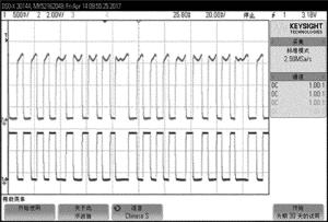
    Figure 2.  Oscillogram after dividing the light through Wollaston prism

    因为当o光、e光在竞争过程中,其中有一束光(假设是o光)获得增益,则o光在竞争中获得优势[7],在波形图中以高电平的形式呈现;而e光未获得增益,所以在波形图中以低电平的形式呈现。而图中o光的凹陷部分是尾端探测由于多次反射造成回馈条纹出现倍频和相位反向的现象[8],经过多次测试后发现凹陷部分并不影响数据的处理结果。

    使用光电探测器分别采集N个o光和e光数据点,使用C语言程序对数据进行统计分析,精确计算其低电平的占空比Y。当偏振态信号中非偏振片通光方向的光强处于最小位置时,两束光的低电平占空比理论值为0.5。但是在实际调节双折射元件的过程中,系统容易受外界因素干扰,低电平占空比的实际值往往不能达到0.5。经过分析重复测试的结果后得到, 对于任意相位延迟的波片,当两束光的低电平占空比Y≥0.47时, 会出现类似于图 2的波形,表明双折射测量系统已经获得较标准的偏振跳变曲线,故本文中选择Y值为0.47。

  • 双折射测量系统的原理图如图 3所示。图中光源为半外腔单模He-Ne激光器,工作波长632.8nm。激光管内充入氦氖气体,He与Ne的气压比为7: 1。M1和M2组成激光器谐振腔,其中M1是反射率r1=0.994、曲率半径ρ=1m的凹面镜,M2是反射率r2=0.989的平面镜。图中,A/D和D/A是模/数(analog/digital)和数/模(digital analog)转换。

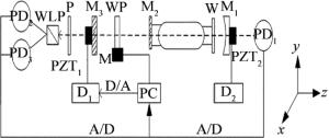
    Figure 3.  Schematic diagram of measurement device

    装置的回馈腔由平面镜M2和M3组成,其中M3是反射率为26%的回馈镜,作用是将部分激光反射回激光谐振腔中[9]。图中, PZT1、PZT2为最大伸长量为0.5μm的压电陶瓷,D1和D2为接收三角波信号的压电陶瓷驱动器。在实验中压电陶瓷PZT1驱动回馈镜,沿激光轴线方向运动,作用是改变激光回馈腔的腔长[10]。本文中选用λ/4波片作为双折射元件(wave-plate, WP)。

    装置的偏振态部分由偏振片P、渥拉斯顿棱镜(Wollaston lens prism, WLP)、计算机(personal computer, PC)以及两个光电探测器(photodetector, PD)PD2和PD3组成。该部分使用渥拉斯顿棱镜进行分光,利用控制及测量程序对o光和e光进行数据处理,继而控制3维平移台M调节波片方位,使波片的快轴方向自动对准激光本征偏振方向[11-12]

    信号处理与波片测量部分是由PD1和计算机组成。为了使系统正常工作,要调节激光腔长,将激光器的光强稳定在最大点处,保持单纵模输出[13]。光电探测器PD1采集偏振跳变点、偏振跳变点右端同周期内的等光强点和两个最小光强点,根据上述偏振跳变点与相位延迟大小的关系式计算波片的相位延迟。

  • 自动控制系统的主要装置是型号为YH42BYGH 47-401的精密平移台,其工作电流在1.5A以内,步距角为1.8°,细分数为16,不但能提供精确的定位,而且电机长时间持续工作的能力保证了系统的稳定性。双折射测量系统中用于调节波片方位的程序流程图如图 4所示。将待测波片放置在3-D平移台上,设置3-D平移台x轴、y轴的移动速率为10mm/s,z轴的速率为18r/min。3-D平移台从初始位置依次沿x轴和y轴方向移动10mm,z轴旋转1转后停止运动;左右两端探测器将采集的数据经A/D转换,传输到计算机的程序处理模块[14],根据低电平的占空比Y判断波片快轴与激光本征偏振方向的对准情况;在调节过程中,当Y < 4.7时,MPC07运动控制卡继续发出脉冲信号控制z轴旋转1转;当Y≥0.4时,由于较小步距的旋转能提高波片快轴的定位精度[15],故z轴进行旋转0.5转的微调;当Y≥0.47时,出现较标准的偏振跳变曲线,调用波片测量程序计算波片相位延迟大小。在第1次测量结束后,控制平移台沿x轴或y轴继续移动5mm并重复上述过程,即可实现在x轴或y轴轴线方向进行多次测量的功能。

    Figure 4.  Flow chart of control program

2.   测量结果
  • 选取一组测量数据对系统在优化前后的波片测量结果进行定量分析[16]图 5是优化后的双折射测量系统获得的偏振跳变图。表 1中分析了波片在不同的调节方式下,出现偏振跳变现象时o光和e光的低电平占空比。

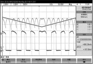
    Figure 5.  Polarization flipping graph after system optimization

    experiment times the traditional way of
    adjusting wave-plate
    the optimized mode of
    adjusting wave-plate
    1 0.4653 0.4762
    2 0.4655 0.4715
    3 0.4685 0.4823
    4 0.4547 0.4712
    5 0.4667 0.4695
    6 0.4675 0.4757
    7 0.4695 0.4707
    8 0.4515 0.4837
    9 0.4682 0.4722
    10 0.4705 0.4812
    average 0.4648 0.4754
    standard deviation 0.0064 0.0053

    Table 1.  Analysis of duty cycle of the low level of ordinary light and extraordinary light

    在测量过程中,系统会受到外界振动、温度、光强、噪声等因素的影响[17-18],o光和e光的低电平占空比不能达到理想值。表 1中的测试结果表明,在优化后的测量系统中低电平的占空比可达0.475以上,较原有的测量系统平均提高1%,标准差降低17%,总体上提高了波片光轴的定位精度。表 2中则对比分析了系统在优化前后波片相位延迟的测量结果。

    experiment
    times
    the measured value of
    the wave-plate before
    the system is optimized/(°)
    the measured value
    of the wave-plate after
    the system is optimized/(°)
    1 89.12 89.66
    2 89.25 90.07
    3 88.77 89.44
    4 89.04 89.54
    5 89.23 89.77
    6 89.07 89.37
    7 89.33 89.75
    8 88.47 89.90
    9 89.42 89.35
    10 89.63 89.58
    average 89.11 89.64
    standard
    deviation
    0.3103 0.2219

    Table 2.  Analysis of the measured value of phase retardation of λ/4 wave-plate

    标准λ/4波片的理论值是在特定环境下的测量值, 但是本文中的测量环境与上述测量环境不一致,这会引入一定的测量误差[19-20]。由表 2中连续测量10次的数据结果表明,在双折射测量系统中增加自动定位波片光轴的控制系统后,波片相位延迟的最大偏差为0.65°,标准差较之前降低28.49%,波片测量系统的测量精度和稳定性同时得到提升。

3.   结论
  • 基于MPC07运动控制卡、YH42BYGH47-401 3-D平移台及程序算法,实现了自动定位波片快轴的功能,提高了激光回馈双折射测量系统的稳定性和可操控性。在一定的测量环境下,由于降低了人为调节波片时可能引入的随机误差和粗大误差,所以双折射测量系统中o光、e光的低电平占空比可达0.475以上,能够快速获得较标准的偏振跳变曲线。这使波片在多次测量过程中平均值得到提高,最大偏差降至0.65°,标准差减小28%,更加接近标准波片的相位延迟值。因此,自动对准波片光轴方位的设计对激光回馈双折射测量系统实现高效率、高精度、高稳定性的工业化测量要求具有实际意义。

Reference (20)

Catalog

    /

    DownLoad:  Full-Size Img  PowerPoint
    Return
    Return