Advanced Search

ISSN1001-3806 CN51-1125/TN Map

Volume 45 Issue 3
May  2021
Article Contents
Turn off MathJax

Citation:

Sub-pixel adaptive center extraction of line structured light stripe

  • Received Date: 2020-06-01
    Accepted Date: 2020-09-04
  • In order to solve the problem that the traditional stripe center extraction algorithm is sensitive to material and noise, an adaptive structured light stripe center extraction algorithm was used to extract the fringe sub-pixel coordinates. The algorithm first preprocesses the image, extracts the region of interest of the stripe image by using the image mask operation, eliminates noise interference through the adaptive convolution template, and obtains the pixel sets of the stripe area cross-sectional width and center coordinates. Secondly, according to the pixel set of the central coordinates, the initial coordinate value of the stripe center was calculated by the quadratic weighted gray centroid method, which will be used as the seed point for regional growth operation, then combined with principal component analysis to decompose the characteristic matrix, and finally the sub-pixel coordinate point of the center of the linear structured light was obtained. The results show that the center sub-pixel coordinates of the structured light stripe can be effectively and quickly obtained by this algorithm. Compared with the gray-scale barycenter method, the extraction results of the algorithm in this paper are less volatile and have a relatively small standard error. The extraction speed is nearly 4 times higher than that of the Steger method based on Hessian matrix, which meets the real-time requirements of the industrial measurement system. The proposed algorithm in this paper has high extraction accuracy, good robustness, low computational complexity, and high real-time performance, which provides nice accuracy guarantee for the subsequent 3-D vision measurement system.
  • 加载中
  • [1]

    HUANG L F, LIU G D, ZHANG Ch, et al. Laser stripe center extraction algorithm based on gray weight model[J]. Laser Technology, 2020, 44(2): 190-195(in Chinese).
    [2]

    HYUN K J, SUNG B I, MIN H C. A digital approach to dynamic jaw tracking using a target tracking system and a structured-light three-dimensional scanner[J]. Journal of Prosthodontic Research, 2019, 63(1): 115-119. doi: 10.1016/j.jpor.2018.05.001
    [3]

    LIU X L, HE D, CHEN H L, et al. Techniques of structured light measurement network with 3-D sensors[J]. Infrared and Laser Engineering, 2020, 49(3): 0303007(in Chinese). doi: 10.3788/IRLA202049.0303007
    [4]

    ZHANG H, ZHAO B X, LIU G H, et al. Design of rail surface defect detection system based on binocular structure light[J]. Process Automation Instrumentation, 2018, 39(4): 92-95(in Chinese).
    [5]

    ZENG D W, XU G L, CHENG Y H, et al. Subpixel extraction of li-near structured light stripe center based on adaptive template[J]. Optoelectronic Technology, 2018, 38(2): 117-121(in Chinese).
    [6]

    NAN F, LI D H, GAO Q, et al. Implementation of adaptive light stripe center extraction of improved Steger algorithm[J]. Laser Journal, 2018, 39(1): 85-88(in Chinese).
    [7]

    ZENG Ch, WANG Sh J, LU H, et al. Center extraction algorithm of line structured light stripe[J]. Journal of Image and Graphics, 2019, 24(10): 1772-1780(in Chinese).
    [8]

    LENG H W, XU Ch G, XIAO D G, et al. A Method for measuring complicated deep-hole profile using line-structured-light sensor[J]. Transactions of Beijing Institute of Technology, 2013, 33(2): 139-143(in Chinese).
    [9]

    WANG Sh Y, LI D H, GAO Q, et al. Detection of structured light strip center line based on improved skeletal removal algorithm[J]. Laser Journal, 2018, 39(10): 39-43(in Chinese).
    [10]

    LI Y, CHENG F, ZHAO Zh L. Machining precision online measurement of large span pin hole using structured light[J]. Journal of Zhejiang University (Engineering Science Edition), 2020, 54(3): 557-565(in Chinese).
    [11]

    LI D, GENG N, KANG J N. Research on laser stripe center extraction algorithm under complex background[J]. Computer Applications and Software, 2013, 30(3): 271-273(in Chinese).
    [12]

    STEGER C. An unbiased detector of curvilinear structures[J]. IEEE Transactions on Pattern Analysis and Machine Intelligence, 1998, 20(2): 113-125. doi: 10.1109/34.659930
    [13]

    LIU J, LIU L H. Laser stripe center extraction based on hessian matrix and regional growth[J]. Laser & Optoelectronics Progress, 2019, 56(2): 021203(in Chinese).
    [14]

    LI F J, LI X J, LIU Zh. A multi-scale analysis based method for extracting coordinates of laser light stripe centers[J]. Acta Optica Si-nica, 2014, 34(11): 1110002(in Chinese). doi: 10.3788/AOS201434.1110002
    [15]

    YANG Zh H, YANG L, LI H, et al. Stripe center extrication algorithm for structured-light in complex environment[J]. Computer Technology and Developmentm, 2018, 28(9): 7-10(in Chinese).
    [16]

    CAI H Y, FENG Zh D, HUANG Zh H. Centerline extraction of structured light stripe based on principal component analysis[J]. Chinese Journal of Lasers, 2015, 42(3): 0308006(in Chinese). doi: 10.3788/CJL201542.0308006
    [17]

    YIN X Q, TAO W, FENG Y Y, et al. Laser stripe extraction method in industrial environments utilizing self-adaptive convolution technique[J]. Applied Optics, 2017, 56(10): 2653-2660. doi: 10.1364/AO.56.002653
  • 加载中
通讯作者: 陈斌, bchen63@163.com
  • 1. 

    沈阳化工大学材料科学与工程学院 沈阳 110142

  1. 本站搜索
  2. 百度学术搜索
  3. 万方数据库搜索
  4. CNKI搜索

Figures(10) / Tables(2)

Article views(5311) PDF downloads(26) Cited by()

Proportional views

Sub-pixel adaptive center extraction of line structured light stripe

  • Department of Automation, School of Electrical Engineering, North China University of Science and Technology, Tangshan 063210, China

Abstract: In order to solve the problem that the traditional stripe center extraction algorithm is sensitive to material and noise, an adaptive structured light stripe center extraction algorithm was used to extract the fringe sub-pixel coordinates. The algorithm first preprocesses the image, extracts the region of interest of the stripe image by using the image mask operation, eliminates noise interference through the adaptive convolution template, and obtains the pixel sets of the stripe area cross-sectional width and center coordinates. Secondly, according to the pixel set of the central coordinates, the initial coordinate value of the stripe center was calculated by the quadratic weighted gray centroid method, which will be used as the seed point for regional growth operation, then combined with principal component analysis to decompose the characteristic matrix, and finally the sub-pixel coordinate point of the center of the linear structured light was obtained. The results show that the center sub-pixel coordinates of the structured light stripe can be effectively and quickly obtained by this algorithm. Compared with the gray-scale barycenter method, the extraction results of the algorithm in this paper are less volatile and have a relatively small standard error. The extraction speed is nearly 4 times higher than that of the Steger method based on Hessian matrix, which meets the real-time requirements of the industrial measurement system. The proposed algorithm in this paper has high extraction accuracy, good robustness, low computational complexity, and high real-time performance, which provides nice accuracy guarantee for the subsequent 3-D vision measurement system.

引言
  • 线结构光3-D视觉测量技术作为一种有效的主动视觉测量方法,具有实时性、非接触、准确度高和等优点[1],在目标跟踪[2]、逆向工程[3]、缺陷检测[4]等领域中广泛应用。传统线结构光测量系统一般由CCD相机、线形激光器、光源以及计算机组成。在线结构光3-D测量系统中,精确提取光条图像的条纹中心坐标是获取被测目标3-D形貌信息至关重要的一步[5]。理想的光条是一条单像素宽的细线[6],但通常线激光具有一定的像素宽度,条纹中心坐标提取的偏差将直接影响被测目标3-D坐标的精度[7]。因此如何实现快速、精确提取结构光条纹中心,对提高线结构光3-D测量系统的精度具有重要意义。

    传统的线结构光条纹中心提取算法包括极值法、灰度重心法[8]、骨架细化法[9]、方向模板法[10]等,具有快速、简单、易实现等特点,但精度无法满足工业测量的需要。大量研究人员对线结构光光条中心提取算法进行了改进,LI等人[11]结合极值法和灰度重心法,实现了复杂背景下条纹中心提取,提高了条纹中心提取的准确性和快速性,但其方法抗噪声能力一般。基于Hessian矩阵的Steger法[12-13]虽然精度较高,但需要进行大量卷积运算,导致计算复杂度提高,难以满足测量系统实时性的要求。LI等人[14]对Steger算法做出改进,提出了一种基于多尺度分析的激光条纹中心提取方法,但在条纹中心提取时,中心点和边缘点之间的距离问题使运算效率降低。

    针对在工业环境下采集的结构光图像较难提取条纹中心的问题,作者提出了一种自适应结构光条纹中心提取方法。该方法在条纹灰度特征的基础上,通过自适应卷积模板有效减弱环境噪声影响,得到条纹图像的感兴趣区域,提高了算法的计算效率,再根据条纹的线宽采用加权灰度重心法提取条纹中心的初始点位置,对初始点进行区域生长运算并构造协方差矩阵,利用主成分分析对其进行特征分解,得到结构光条纹中心的亚像素坐标,并比较分析了不同条纹中心提取方法的精度与运行时间。

1.   基本原理
  • 激光产生的基本原理是大量粒子的受激辐射的现象[15]。线激光器通过将柱面镜和球面镜组合产生一种单色线激光。理想情况下,激光能量在光条截面上呈现对称高斯分布,激光条纹图像灰度值最大点就是条纹中心点。

    由于被测物体材质以及噪声等因素的影响,如材料的表面粗糙度、透明度、均匀性等,使得被测物体表面对光的反射率并不均匀。这种偏差导致激光条纹截面的光强分布发生改变,从而使条纹图像截面的灰度值呈不对称的近似高斯分布。

    图 1为实际采集的线结构光条纹图像及其分析过程。图 1a结构光条纹原始图像中含有噪声等因素造成的干扰;图 1b为条纹图像截面对应的灰度值分布,伴有较为明显的干扰;图 1c为阈值分割后的条纹图像,图像中除了干扰以外,条纹本身出现断续状况;图 1d为原始条纹图像x轴中心线方向对应的红绿蓝(red, green, blue, RGB)灰度值变化情况。可知,由于像素灰度值的不连续,导致了光条图像分割后出现断续现象。因此, 需要利用数字图像处理技术对采集的原始激光条纹图像进行区域限定及干扰消除等操作。

    Figure 1.  Linear structured light stripe image and grayscale distribution

  • 采用5×5模板的中值滤波用于抑制条纹图像中的噪声,对滤波后的图像使用最大类间方差法来得到图像分割的最佳阈值,并根据此阈值对条纹图像进行全局二值化操作,可以表示为:

    式中,t表示为最佳分割阈值,g(x, y)为条纹图像像素点灰度值,I(x, y)为二值化后的像素点灰度值。将二值化后的图像作为掩模,并与条纹灰度图像进行乘法运算,得到条纹图像初始感兴趣区域,其公式为:

    式中,G(x, y)表示条纹图像初始感兴趣区域。使用掩模操作可以很大程度消除条纹图像中的干扰,在保留条纹图像灰度特征的基础上,同时也能达到获取感兴趣区域的目的。图像掩模操作如图 2所示。

    Figure 2.  Mask operation of laser stripe image

  • Steger法将图像视为2维函数,利用Hessian矩阵计算特征值和特征向量,得到条纹中心坐标的法线方向,并在法线方向上将条纹灰度分布根据泰勒多项式展开,获取对应法线上的极值点,即在条纹截面灰度分布曲线上1阶导数为0,2阶导数为负数的极小值点,为所求取得条纹截面中心亚像素点。通过求取线结构光条纹图像像素点Hessian矩阵的特征值及其对应的特征向量来得到光条中心点法线方向[10]。Hessian矩阵表示为:

    式中,S(x, y)为2维高斯函数; rxx, rxy, ryy分别为高斯函数的2阶导数和2阶偏导数与图像的卷积。以(x0, y0)为中心点,其对应法线方向上的单位向量为n=(nx, ny),对线结构光条纹截面灰度分布函数沿单位向量方向进行2阶泰勒展开,则条纹截面中心点(x0+tnx, y0+tny)的像素值可表示为:

    式中,rxry分别为对应微分形式的高斯函数与G(x, y)卷积得到,表示为:

    结构光条纹中心坐标满足约束条件(tnx, tny)∈$\left[ { - \frac{1}{2}, \frac{1}{2}} \right] \times \left[ { - \frac{1}{2}, \frac{1}{2}} \right]$以及$\frac{{\partial \mathit{\boldsymbol{G}}(x, y)}}{{\partial t}} = 0$,可得最佳分割阈值t

    式中,条纹中心点亚像素坐标为(x0+tnx, y0+tny)。

    由于Hessian矩阵运算量大,其中每个像素点都要进行5次(rx, ry, rxy, rxx, ryy)2维高斯卷积运算,导致Steger算法计算效率低,造成系统实时性下降。

    本文中在保证线结构光条纹中心提取精度的基础上,基于Steger算法,利用主成分分析法[16]对协方差矩阵进行特征分解,求得特征值与特征向量,从而达到减小Steger算法的计算量、提高计算效率的目的。

2.   线结构光条纹中心坐标提取
  • 线结构光条纹中心亚像素提取的主要流程如图 3所示。

    Figure 3.  Flow chart of stripe center extraction

    (1) 通过最大类间方差法与图像掩模操作得到条纹图像感兴趣区域,保留了条纹图像灰度特征;(2)利用自适应卷积模板对感兴趣区域进行去噪处理,并求得条纹中心坐标的像素集合;(3)根据中心坐标的像素集合,应用二次加权灰度重心法提取条纹中心的初始点; (4)根据条纹中心坐标初始点,利用区域增长法得到条纹中心坐标的小范围区域,使用主成分分析代替多次求解高斯卷积过程求得条纹中心亚像素坐标。

  • 在线结构光条纹图像采集过程中,由于环境因素以及相机性能的影响,对条纹图像进行中值滤波和掩模操作往往不能有效消除噪声干扰。因此,要对条纹图像进行进一步去噪处理,最小化噪声对提取结果准确性的影响。为便于观察,将掩模后的条纹灰度图像进行二值化操作,如图 4所示。噪声尚未被完全消除,其结果将会导致条纹中心提取精度下降。

    Figure 4.  The noise of laser stripe image

    本文中结合传统激光条纹中心提取方法对噪声敏感的特点,基于激光条纹的几何特征及其相关性[17],采用自适应卷积模板来解决此问题。首先计算自适应卷积模板的大小,自适应模板的大小和参量值取决于激光条纹的几何信息和相关性,其获取流程如图 5所示,通过图像与模板进行卷积操作达到去除噪声的目的。

    Figure 5.  The flow chart of adaptive convolution template algorithm

    图 5中,模板行数为R, 模板列数为C, 模板中心行元素设置为k, 模板其余元素设置为λk, λ为系数。对掩模后的灰度图像逐列搜索灰度值大于零的像素点,可获得条纹感兴趣区域截面上下边界的像素点坐标值,并根据其坐标求出每列的宽度Di,得到最大的截面宽度wm,统计条纹截面非零列的数量,可得出条纹的长度L,条纹宽度均值wp=∑Di/L,条纹截面宽度周围噪声区域可表示为(wm-wp),λ的取值小于1,用于减弱噪声区域,令矩阵元素的总和为1,可得到参量k值。

    条纹感兴趣区域经过自适应卷积模板处理后,如图 6所示。可以发现, 噪声得到明显减弱,条纹轮廓得到了较好保留。通过掩模操作,获得感兴趣条纹区域,并利用自适应卷积模板,有效地消除了噪声对条纹中心提取的干扰,能够提高光条提取精度,满足测量系统的准确性要求。

    Figure 6.  Image processed by adaptive convolution

  • 由于被测物体材质影响,导致线结构光光强分布不均,条纹截面宽度并不一致,通过检测条纹的上下边界,即每列中的最上和最下的非零灰度值对应点的坐标值,并将其记为(xi, yi, u)和(xi, yi, d),可以得到条纹截面每列中心坐标所在的像素集合,采用二次加权灰度重心法提取条纹中心的初始位置,可以表示为:

    式中,g(xi, y)为图像中的第xi行第y列坐标点的灰度值,条纹每列截面宽度Di=yi, d-yi, uyi, uyi, d分别为条纹截面上下边界的像素坐标。

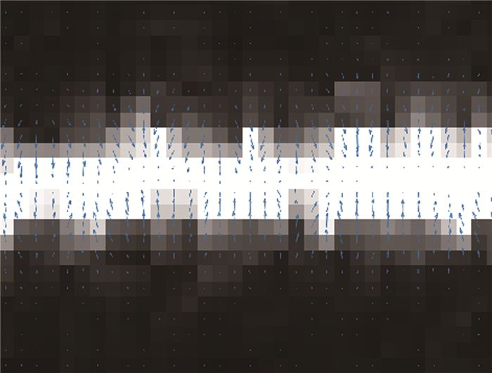
  • 线结构光条纹在其法线方向上梯度最大,而在其条纹方向上梯度最小,条纹区域中像素点法向量的方向变化较小,如图 7所示。在一个较小的条纹区域内,像素点法向量方向变化较小,因此可利用此区域的平均梯度值来求条纹的法线方向。

    Figure 7.  Stripe region gradient

    首先将加权灰度重心法提取条纹中心坐标初始值作为区域生长的种子点,将灰度阈值设为生长准则,以种子点为中心遍历周围八邻域像素值,确定下一种子点。沿条纹方向生长点周围八邻域定义为生长连通域,通过判断像素点灰度差值,将小于灰度阈值的点归为一个连通域,可以有效防止过度生长。

    区域生长完成后,该区域内的梯度向量为,构建协方差矩阵,其次利用主成分分析对其进行特征分解[16],求解特征值与特征向量,条纹的法向为绝对值最大的特征值对应的特征向量。

    最后,使用泰勒2阶展开求得条纹中心点亚像素坐标位置,有效避免了使用Hessian矩阵多次求解高斯卷积的过程。由于线结构光条纹图像在法线方向上呈不对称的近似高斯分布,高斯核参量σ的选取直接影响条纹中心的提取效果,结合Steger算法,本文中的高斯核参量σ大小设为:

3.   实验结果与分析
  • 实验在CPU为Inetel-5500U、RAM为8G的计算机上利用MATLAB2019a软件编程实现,使用Allied Vision Technologies公司生产的Mako G-192C相机。为了验证本文中所提方法的有效性与准确性,将实验结果与传统灰度重心法和基于Hessian矩阵的Steger法得到的实验结果进行主观评价与客观评价,其中,图像大小为378pixel×300pixel,滤波器模板大小均为5×5,Steger法的高斯核参量设置为σ=15/$\sqrt 3 $。

  • 不同方法提取的条纹中心线如图 8所示。图 8a~图 8d分别为原始条纹的灰度图像、灰度重心法提取结果、Steger法提取结果、本文中的方法提取结果。为便于观察条纹中心提取效果,图 8e~图 8h依次为其局部放大图像。由图 8可知,灰度重心法提取的条纹中心波动较为明显,Steger法提取的条纹中心存在大量光条外点,需要后期通过曲线拟合方法进行消除,增大了计算量,但相比灰度重心法,Steger法提取到的条纹中心较为平整,但这两种方法与理想的条纹中心均存在着一定偏离。本文中方法提取结果波动性最小,且不存在光条外点,更加接近于理想的条纹中心。

    Figure 8.  Center line of laser stripe image by different method

    为进一步验证所提算法的有效性,分别对存在条纹分叉以及散斑噪声干扰的图像提取中心坐标。图 9为条纹分叉情况下提取的条纹中心。灰度重心法提取结果波动明显,Steger法提取结果存在较大的误差,而所提方法提取结果较为平滑。图 10是存在散斑噪声干扰情况下提取的条纹中心。由于图像灰度分布不均,灰度重心法提取结果上下波动最为剧烈,Steger法提取结果则存在大量的光条外点,而所提方法由于去除了噪声干扰,提取结果较为平滑。

    Figure 9.  Center line of laser stripe crossing image

    Figure 10.  Center line of laser stripe image with speckle noise interferes

  • 图 1b可知,噪声干扰严重影响条纹图像x轴的灰度值分布,降低条纹中心坐标的提取精度。存在条纹分叉的图像在交叉处也会降低提取中心坐标的准确性。

    为进一步评价所提算法的准确性,利用提取到的条纹中心点x坐标到条纹中心真值x坐标的标准误差表示算法提取中心点的准确度。由于条纹中心真值无法测得,导致真差未知,通常使用残差$\left( {{x_i} - \bar x} \right)$来代替真差,根据贝塞尔公式,条纹中心点x坐标标准误差可以表示为:

    式中,n为提取的中心点个数;x表示中心点的x坐标平均值。表 1为提取到的3种条纹图像中心x坐标的标准误差。理想情况、分叉情况以及散斑噪声干扰下的图像标准误差依次对应表 1中的s1, s2s3,理想情况为不存在条纹分叉以及噪声干扰较小的图像。表中加粗字体表示最优值。

    methodgray centroid
    method/pixel
    Steger method/
    pixel
    the proposed
    method/pixel
    s187.352881.081080.9546
    s22.26284.10152.0966
    s37.07232.78912.5715

    Table 1.  The standard error of extraction methods of light strip center line

    表 1可知,对比其它两种方法,本文中所提方法由于去除了条纹图像中大量噪声,将条纹中心的初始点进行区域生长运算,提高了条纹中心坐标的提取精度,标准误差最小,准确度相对较高。

    线结构光条纹中心坐标提取作为实现3-D视觉检测系统的关键技术之一,需要满足工业环境下实时性要求,因此, 条纹中心提取算法的运行时间是检测算法实用性的一项重要指标。采用5张线结构光条纹图像分别使用上述提取方法,每张图片运行10次,3种方法提取条纹图像中心坐标的平均运行时间如表 2所示。

    methodgray centroid
    method/s
    Steger
    method /s
    the proposed
    method/s
    10.31471.73050.4128
    20.42971.75280.4981
    30.35711.66750.4219
    40.41881.65040.3636
    50.33571.70950.3837

    Table 2.  Average running time of extraction methods of light strip center line

    表 2可知,本文中的方法平均运行时间较快,与灰度重心法相差不大,但优于Steger法运行时间。本文中使用主成分分析求解协方差矩阵代替Hessian矩阵的求解过程,无需进行大量高斯卷积运算,在保证提取精度的条件下,计算复杂度相对较小。

4.   结论
  • 在线结构光条纹法线方向灰度分布的基础上,结合激光条纹几何特征及其相关性,提出一种新的条纹中心坐标提取方法,实现了条纹中心线快速精确提取。所提方法首先利用掩模操作对图像进行预处理,使用自适应卷积模板有效地降低了噪声对图像的干扰,同时得到条纹区域截面中心坐标的像素集合,以及条纹宽度的平均值,使用二次加权灰度重心法提取条纹中心初始坐标点,利用区域生长与主成分分析得到条纹中心的亚像素坐标点。本文中的方法相比Steger法,无需进行大量卷积运算,计算复杂度低且精度可达到亚像素级,提取速度提高约4倍,可以满足工业测量系统的实时性要求,相比灰度重心法,该方法稳健性强且精度较高。后期将对图像背景过亮、线结构光条纹不均匀等情况,展开深入研究。

Reference (17)

Catalog

    /

    DownLoad:  Full-Size Img  PowerPoint
    Return
    Return