Advanced Search

ISSN1001-3806 CN51-1125/TN Map

Volume 45 Issue 6
Nov.  2021
Article Contents
Turn off MathJax

Citation:

Calibration technology of laser-induced damage threshold of thin films

  • Received Date: 2020-11-09
    Accepted Date: 2020-11-24
  • In order to meet the requirements of objective, accurate, and high-precision measurement of laser damage threshold of thin films, the calibration technology of damage threshold was proposed. Firstly, the experimental calibration method of exchanging the positions of the two energy detectors was used to eliminate the error of the spectroscope and the measurement of the energy detector, so as to obtain the accurate irradiation energy. Then, the measurement method of adjusting the positions of two CCD devices to obtain the same spot size was used to calibrate the equivalence between the measured sample surface and the spot area measurement surface, and the non flat top part of the laser spot was eliminated, so as to obtain the accurate irradiation spot area. Finally, the least square method was used to fit the calculated energy density and the corresponding damage probability to obtain the damage threshold. The 1064nm laser irradiation experiment of TiO2/SiO2 high reflection film was carried out, and the laser damage threshold was 23.0164J/cm2. The results show that the measurement accuracy of laser damage threshold is increased by 9.26% by using calibration technology, which meets the high precision measurement requirements. This study is helpful for accurate calibration of laser damage threshold of thin films.
  • 加载中
  • [1]

    SHAN C, ZHAO Y A, ZHANG X H, et al. Study on laser damage threshold of optical element surface based on gaussian pulsed laser spatial resolution[J]. Chinese Journal of Lasers, 2018, 45(1): 0104002(in Chinese). doi: 10.3788/CJL201845.0104002
    [2]

    LING X L, LIU Sh H, LIU X F. Enhancement of laser-induced damage threshold of optical coatings by ionbeam etching in vacuum environment[J]. Optik, 2020, 200: 163429. doi: 10.1016/j.ijleo.2019.163429
    [3]

    VIKTÓRIA C, ZSOLT B, NAGY B J, et al. Ultrafast multipulse damage threshold of femtosecond high reflectors[J]. Applied Optics, 2018, 57(2): 340-343. doi: 10.1364/AO.57.000340
    [4]

    KUMAR S, SHANKAR A, KISHORE N, et al. Laserinduced damage threshold study on TiO2/SiO2 multilayer reflective coatings[J]. Indian Journal of Physics, 2020, 94: 105-115. doi: 10.1007/s12648-019-01445-3
    [5]

    LI Y Y, ZHANG W Y, LIU Zh, et al. Cumulative effect of thin film laser damage under S-on-1 measurement mode[J]. Laser Technology, 2018, 42(1): 39-42(in Chinese).
    [6]

    TALBI A, SEMMAR N, TABBAL M, et al. Femtosecond laser irradiation of titanium oxide thin films: Accumulation effect under IR beam[J]. Applied Physics, 2020, A126(5): 390. doi: 10.1007/s00339-020-03568-5
    [7]

    LING X L, LIU Sh H, LIU X F, et al. The effect of water vapor on nanosecond laser damage resistance of optical coatings in vacuum[J]. Optik, 2018, 164: 654-660. doi: 10.1016/j.ijleo.2018.03.084
    [8]

    WANG H X, SHEN L, LI Ch F, et al. Analysis and experimental investigation of laser induced damage of optics[J]. Chinese Journal of Lasers, 2017, 44(3): 0302006(in Chinese). doi: 10.3788/CJL201744.0302006
    [9]

    GE J M. Analysis and diagnosis on optical film laser damage[D]. Nanjing: Nanjing University of Sciences and Technology, 2018: 101-106(in Chinese).
    [10]

    LAMAIGNERÈ L, VEINHARD M, TOURNEMENNE F, et al. A powerful tool for comparing different test procedures to measure the probability and density of laser induced damage on optical materials[J]. Review of Scientific Instruments, 2019, 90(12): 125102. doi: 10.1063/1.5122274
    [11]

    KUMAR S, SHANKAR A, KISHORE N, et al. Laser-induced damage threshold study on TiO2/SiO2 multilayer reflective coatings[J]. Journal of Cleaner Production, 2020, 94(1): 105-115.
    [12]

    CHENG Y, LU Y M, TANG H, et al. Researches on laser damage resistance of optical films[J]. High Power Laser and Particle Beams, 2016, 28(7): 070201(in Chinese).
    [13]

    ZHENG Y L, HU Y H, ZHAO N X, et al. Analysis of the influence of pulse width and repetition frequency on damage threshold of HgCdTe detector[J]. Laser Technology, 2018, 42(2): 265-270(in Chinese).
    [14]

    WANG F, LI Y Y, CHE Y, et al. Measurement system of flattop laser induced damage threshold to film[J]. Acta Photonica Sinica, 2016, 45(3): 0314003(in Chinese). doi: 10.3788/gzxb20164503.0314003
    [15]

    GUO K Sh, WANG Y Zh, CHEN R Y, et al. Effects of structural defects on laser-induced damage of 355-nm high reflective coatings sputtered on etched substrates[J]. Optical Materials, 2019, 89: 173-177. doi: 10.1016/j.optmat.2018.12.024
    [16]

    YIN J H, CAO Y ZH, YAN Y D, et al. Laser-induced damage of black glass before and after surface treatment by containing impurities-SiO2 film during ultra clean manufacturing [J]. Journal of Cleaner Production, 2020, 257: 120360. doi: 10.1016/j.jclepro.2020.120360
    [17]

    YAO J K, YE F, FAN P, et al. Ultraviolet laser damage mechanisms of amorphous InGaZnO4 thin films[J]. Optical Materials Express, 2019, 9(6): 2545-2552. doi: 10.1364/OME.9.002545
    [18]

    XU J Q, SU J H, GE J M, et al. Measurement uncertainty of laser-induced damage threshold of the optical thin films[J]. Infrared and Laser Engineering, 2017, 46(8): 0806007(in Chinese). doi: 10.3788/IRLA201746.0806007
    [19]

    WANG G X, SU J H, XU J Q, et al. Misjudgment elimination method on identification of thin film damage by plasma flash method[J]. Spectroscopy and Spectral Analysis, 2018, 38(11): 3341-3346(in Chinese).
  • 加载中
通讯作者: 陈斌, bchen63@163.com
  • 1. 

    沈阳化工大学材料科学与工程学院 沈阳 110142

  1. 本站搜索
  2. 百度学术搜索
  3. 万方数据库搜索
  4. CNKI搜索

Figures(5) / Tables(1)

Article views(10032) PDF downloads(27) Cited by()

Proportional views

Calibration technology of laser-induced damage threshold of thin films

  • 1. School of Life Science and Technology, Changchun University of Science and Technology, Changchun 130022, China
  • 2. School of Opto-Electronic Engineering, Changchun University of Science and Technology, Changchun 130022, China
  • 3. Xi'an Kangben Material Co. Ltd., Xi'an 710089, China

Abstract: In order to meet the requirements of objective, accurate, and high-precision measurement of laser damage threshold of thin films, the calibration technology of damage threshold was proposed. Firstly, the experimental calibration method of exchanging the positions of the two energy detectors was used to eliminate the error of the spectroscope and the measurement of the energy detector, so as to obtain the accurate irradiation energy. Then, the measurement method of adjusting the positions of two CCD devices to obtain the same spot size was used to calibrate the equivalence between the measured sample surface and the spot area measurement surface, and the non flat top part of the laser spot was eliminated, so as to obtain the accurate irradiation spot area. Finally, the least square method was used to fit the calculated energy density and the corresponding damage probability to obtain the damage threshold. The 1064nm laser irradiation experiment of TiO2/SiO2 high reflection film was carried out, and the laser damage threshold was 23.0164J/cm2. The results show that the measurement accuracy of laser damage threshold is increased by 9.26% by using calibration technology, which meets the high precision measurement requirements. This study is helpful for accurate calibration of laser damage threshold of thin films.

引言
  • 目前,高功率激光器已应用于军事、医疗、航空航天、电子和通讯等各个科学技术领域,光学薄膜的损伤已经成为限制激光系统输出更高功率的主要因素,提高薄膜激光损伤阈值是高功率激光器发展的必然要求。因此,薄膜激光损伤阈值快速、准确、客观的测量具有极其重要的意义[1-2]

    近年来,薄膜激光损伤阈值测量相关技术在国内外发展很快[3-8]。2018年,南京理工大学的SU等人研究了光学薄膜激光诱导损伤的识别和准确测试技术,并提出了对薄膜施加外加偏置电场的方法减轻薄膜的激光诱导损伤程度以提高其损伤阈值[9]。2019年,法国的LAMAIGNÈRE等人提出分别采用大光束和小光束对同一光源辐照测量的结果进行比较,实验证明两组测量结果具有一致性[10]。同年,印度的KUMAR等人分别将1064nm和532nm的激光作用于不同层数反射膜上,研究了多层膜对高、低折射率材料薄膜损伤阈值的影响[11]

    损伤阈值是基于辐照在被测薄膜表面的激光能量密度与损伤几率之间的关系确定的,而能量密度又与辐照激光能量和光斑的面积有关[12-13]。因此,首先要研究激光能量的标定和光斑面积的测量问题;然后根据计算得到的激光能量密度与损伤几率的关系进行拟合得到损伤阈值。本文中提出基于平顶激光束辐照测量的薄膜激光损伤阈值标定技术,考虑分光镜的分光误差和能量探测器的测量误差,对辐照的激光能量进行标定;考虑光斑非平顶部分误差和光斑测量等效位置误差,对辐照的光斑面积进行标定。通过以上标定方法,能够获得更准确的能量密度值,从而更加准确、客观地获得薄膜激光损伤阈值。

1.   薄膜激光损伤阈值测量原理
  • 图 1为薄膜激光损伤阈值测量原理图。脉冲激光器输出的激光束经过能量调节器实现脉冲能量的精密调节,出射的激光束经过光束整形聚焦单元后在焦平面上获得平顶分布的聚焦光斑,再经过分光镜A分成两束光,反射光聚焦入射到被测样品表面,透射光被能量密度标定单元接收,且保证光斑测量单元探测面与光束整形聚焦单元的焦平面重合。根据分光镜的分光比例来获得入射到被测样品表面的激光脉冲能量密度;损伤判识单元采集样品表面图像进行处理来判断薄膜是否发生损伤。在同一辐照能量密度下测量不少于10次,最终根据不同光辐照能量密度下被测样品的损伤几率曲线来获得光学薄膜的激光损伤阈值。

    Figure 1.  Principle of laser damage threshold measurement for thin films

2.   辐照激光能量密度的标定
  • 辐照激光能量标定光路如图 2所示。激光束经分光镜A,一部分反射辐照在被测样品表面,另一部分透射到分光镜B,分光镜B将一部分激光能量反射到能量探测器供能量测量,另一部分透射供辐照光斑面积测量。

    Figure 2.  Calibration of optical path by irradiation laser energy

    为了计算辐照在被测样品表面激光能量与探测器所测量激光能量之间的关系,设分光镜A和分光镜B的分光比(透射部分与反射部分能量之比,即P=TR)分别为PAPB,其中PT, APR, A为分光镜A透射部分和反射部分能量,PT, BPR, B为分光镜B透射部分和反射部分能量,则:

    根据(1)式、(2)式和(3)式可得:

    因此,已知两分光镜的分光比PAPB,以及能量探测器示值PR, B,即可计算得到辐照在被测薄膜表面的激光能量PR, A

    以上能量探测器示值与被测样品表面能量值比值的获得是理论计算得到的,并没有考虑分光镜的分光误差和能量探测器的测量误差。因此,为了消除这部分误差需要对比例关系进行试验标定。具体标定方法为:采用两个能量探测器C和D,它们的示值分别用ECED表示,将其分别放置在能量探测器位置和被测样品位置附近,对激光器发出的同一个激光脉冲能量进行测量,则E1=EC, 1ED, 1;为了消除能量探测器本身的测量误差,将C和D的位置互换重新测量,则E2=ED, 2EC, 2。取两次测量的平均值作为比例关系的标定值,即:

    通过以上方法,对能量探测器示值与被测样品表面辐照能量之间的实际比例关系进行标定,校正了分光镜的分光误差和能量探测器的测量误差。根据这一比例关系,通过能量探测器的示值PR, B,标定出每个激光脉冲作用时对应的被测样品表面的实际辐照能量。

  • 辐照光斑面积的标定包括光斑面积的准确测量和测量位置的标定两部分。激光光斑面积的准确测量对薄膜激光损伤阈值的测量精度具有重要意义,常用的测量方法中,相纸削波法和刀口扫描法的测量分辨率较低,线阵旋转扫描法只适用于连续激光的光斑测量,光纤探针扫描法不适用于大尺寸光斑的测量,因此电荷耦合器件(charge-coupled devices,CCD)测量法应用更广泛。

    根据ISO11254-1.2的测试要求,当激光光束的空间分布稳定时,有:

    式中,Q为激光的总能量,Hmax为最大峰值能量密度,Aeff为光斑有效面积, H(x, y)为能量密度。

    以上计算的前提是将激光能量等效为以最高峰值为顶点的均匀分布,该均匀分布的范围即为有效光斑面积[14]。CCD成像法是将被测激光光斑的全部能量直接辐射到CCD的光敏面上测量总能量Q;激光光斑的峰值能量密度Hmax是通过采集每个像元的最大峰值能量除以像元的面积得到的。根据(6)式可计算得到激光光斑的有效面积Aeff

    CCD的像素分辨率决定了光斑面积的精度,为避免高能量激光对CCD探测面的损伤,需要对光能量进行衰减。该方法对于空间能量非高斯型分布的激光光斑测量具有很高的准确性。本系统测试用激光能量服从平顶分布,因此将CCD探测器表面放置在被测样品表面等效位置,光敏面上获得光斑面积即为辐照在被测薄膜表面激光光斑面积。

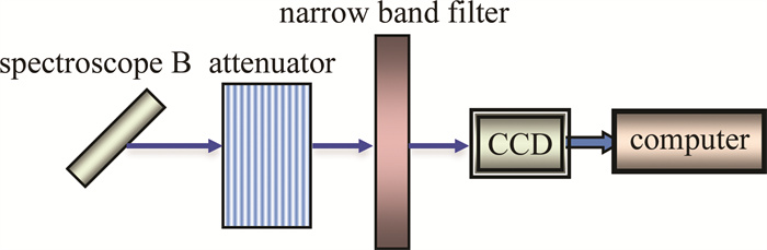
    CCD探测器表面非常敏感,对1064nm波长激光的典型饱和密度大约为9nJ/cm2,当用于面积测量的激光束直接辐照在其表面时,容易使CCD饱和,甚至超过其损伤阈值而导致CCD器件损坏,因此,需要对入射到CCD探测面上的光束进行衰减,直到CCD能够在线性区域范围内工作。测量时,环境的背景光波段较宽,而CCD对可见光的光谱响应灵敏度要比1064nm高得多,因而背景光容易使CCD处于饱和状态,影响测量的精度。为了解决以上问题,需要采用针对1064nm波长的窄带滤光片,主要透过1064nm波长的脉冲激光,滤除掉其它波长的光。测量原理如图 3所示。系统由衰减器、窄带滤光片、CCD探测器和上位机等组成,从分光镜B透射的激光束经衰减后再经窄带滤光片在光敏面上形成光斑,CCD输出的图像视频信号输入计算机供显示、存储、测量和分析。

    Figure 3.  Diagram of flat top beam spot area measurement

    为了准确测量激光光斑的面积,需要CCD在规定的时间开启快门以记录激光脉冲图像,因此需要解决脉冲同步问题。由于激光器的脉冲宽度只有几到十几纳秒,采用连续拍摄的方法无法捕捉到一个完整的脉冲光斑图像,这将导致光斑面积的测量产生较大的误差。为保证采集到的光斑图像是连续、完整的,CCD的电子快门需要采用外触发同步控制的方式。为保证CCD相机有效捕获激光脉冲信号,利用激光电源向脉冲激光二极管(laser diode,LD)提供抽运脉冲作为外同步触发信号,在激光电源向激光器提供抽运能量的同时也发出一个同步触发信号给CCD相机,从而实现激光脉冲的有效捕获。由于从抽运脉冲开始到输出调Q脉冲,持续时间取决于延时电路的延时时长,根据激光器的抽运脉冲宽度设置CCD相机的积分时间。

    光斑面积测量光路中,CCD探测面位置与被测样品表面位置的等效性影响光斑面积的测量精度,进而影响损伤阈值的测量精度,因此需要对等效位置进行标定。具体方法为:将两个CCD相机1和2分别放置在样品测量光路和光斑面积测量光路中;将相机1上下移动,找到CCD探测面上光斑尺寸最小的位置,即聚焦光学系统的焦平面,测量此时光斑尺寸;将相机2左右移动,找到CCD探测面上光斑尺寸与相机1测量结果相同的位置;标定相机1此时的位置为被测样品位置,相机2此时的位置为光斑测量装置中与被测样品的等效位置。标定完成后,此次测量试验中,样品位置与光斑测量光路中CCD探测面位置等效,位置不再移动。

  • 根据辐照激光能量PR, A、测得的光斑面积S以及光束平顶部分所占能量比例η,可以计算得辐照的激光能量密度为:

    首先,计算辐照在样品表面的的激光能量,根据实际标定的能量探测器示值与辐照在样品表面的激光脉冲能量的比例关系,标定出此时辐照在样品表面的激光脉冲能量。辐照到样品表面的激光脉冲能量中只有比例为η的平顶部分能量,计算时只用平顶部分包络的激光脉冲能量值。然后,根据平顶激光束光斑面积的测量原理,通过精确同步控制被测样品表面与CCD探测面位置等效,测量激光光斑的直径,计算得到光斑面积。

3.   损伤阈值的拟合及标定
  • 零几率损伤阈值的确定需要根据激光能量密度与损伤几率的关系建立坐标,横坐标表示激光能量密度,纵坐标表示每个能量密度所对应的损伤几率,对这些离散点进行拟合,该拟合曲线与横坐标的交点所对应的能量密度就是损伤阈值。常用的拟合方法有拉格朗日插值法、牛顿插值法、埃尔米特插值法和最小二乘法等,其中最小二乘法拟合是通过最小化误差的平方和以寻找数据的最佳函数匹配[15-16]

    给定数据点的坐标(xi, yi),其中i=1, 2, …, m。求解近似曲线y=p(x),并使得近似曲线与实际曲线y=f(x)的偏差最小。近似曲线在点(xi, yi)处的偏差为:

    当按照偏差平方和最小的原则选取拟合曲线时,有:

    Φ为次数不超过n(nm)的多项式所构成的函数类,现求$ {p_n}\left( x \right) = \sum\limits_{k = 0}^n {{a_k}{x^k} \in \mathit{\Phi }} $,使得:

    满足(10)式的p(x)为最小二乘拟合多项式,当n=1时,为线性拟合或直线拟合。

    (10) 式为(a0, a1, …, an)的多元函数,其求解即为求I=I(a0, a1, …, an)的极值问题。根据多元函数求极值的必要条件,得:

    即:

    (12) 式为关于(a0a1,…,an)的线性方程,用矩阵表示为:

    方程组(13)的系数矩阵为对称正定矩阵,故存在唯一解,解出ak(k=0,1,…,n),可得多项式:

    在实验测试中,有时采用线性拟合可以合理地得到损伤阈值,但大多数测试采用线性拟合得到的损伤阈值结果与实际阈值偏差较大,因此,采用非线性拟合更接近实际的阈值[17]

  • 损伤阈值的计算流程如图 4所示。输入计算得到的激光能量密度值与其对应的损伤几率,并对损伤几率非零非百的有效数据点进行最小二乘法拟合,求取曲线方程为:

    Figure 4.  Flow chart of damage threshold calculation

    式中,x为能量密度,y为损伤几率。当y=0时对应的x值即为损伤阈值。

4.   损伤阈值测量实验
  • 实验中采用的样品为电子束蒸发技术制备的TiO2/SiO2高反射膜,采用1064nm波长激光辐照,测得光斑直径为755μm,采用上述方法得到光斑面积为4.48×10-3cm2,并计算出每次辐照的激光能量密度。表 1中为辐照激光能量密度与损伤几率之间对应的测量数据。*为拟合可用数据。

    number energy density/(J · cm-2) damage probability/%
    1 2.25 0
    2 44.36 100
    3 23.3 0
    4* 33.87 90
    5* 33.08 90
    6* 32.16 80
    7* 31.54 75
    8* 30.49 65
    9* 29.02 45
    10* 28.11 45
    11* 27.15 30
    12* 26.38 25
    13* 25.47 15
    14* 24.66 15
    15* 23.42 5

    Table 1.  Measurement data of antireflection film

    根据以上测量数据,采用最小二乘法对测量结果进行拟合得损伤阈值为23.0164J/cm2,如图 5所示。

    Figure 5.  Measurement fitting curve

    若未进行上述标定,则会引入一系列影响测量精度的因素[18-19]。其中,两分光镜的分光误差为±0.5%、能量探测器的测量误差为±5%、光斑非平顶部分占比为7.7%、光斑测量等效位置误差为1%。根据方和根法,对以上误差合成:

    因此,薄膜激光损伤阈值标定技术使测量精度提高了9.26%。

5.   结论
  • 本文中针对薄膜激光损伤阈值测量过程中客观、准确、高精度的要求,提出了损伤阈值标定技术。首先,介绍了基于平顶激光束辐照的薄膜激光损伤阈值测量原理。其次,分别对辐照能量和辐照面积进行标定,获得准确的辐照激光能量密度。然后,针对测量的能量密度及其对应的损伤几率进行拟合标定。最后,进行了TiO2/SiO2高反射膜1064nm激光辐照测量实验,测得损伤阈值为23.0164J/cm2,并分析计算得到标定技术使测量精度提高了9.26%,满足客观、准确的测量要求。

Reference (19)

Catalog

    /

    DownLoad:  Full-Size Img  PowerPoint
    Return
    Return