Advanced Search

ISSN1001-3806 CN51-1125/TN Map

Volume 45 Issue 6
Nov.  2021
Article Contents
Turn off MathJax

Citation:

Technical research on testing the quality of parabolic mirror

  • Corresponding author: CHEN Peifeng, pfchen@hust.edu.cn
  • Received Date: 2020-11-10
    Accepted Date: 2020-12-23
  • In order to inspect the quality of the small-size parabolic mirrors, the focal length was measured by the parallel light focusing method, the eccentric angle was measured by rotating the measured mirror.The size of the dispersion spot was measured by combing with the image processing method, and a reduction measurement was proposed.Theoretical analysis and experimental verification of these measurement methods were carried out.The focal length, eccentric angle and size of the diffuse spot of the mirror under test were obtained. The results show that the relative error of the focal length is within 0.1%, the error of the eccentric angle is within 7%, the size of the dispersion spot is less than 0.2mm, and the measurement result is reliable. The design of this scheme provides a good idea for the detection of other small-caliber aspheric surfaces, and provides a good research method for reducing measurement errors and improving measurement accuracy.
  • 加载中
  • [1]

    BOTHE T, LI WS, JUPTNER W P O, et al. High-resolution 3D shape measurement on specular surfaces by fringe reflection [J]. Proceedings of the SPIE, 2004, 5457: 411-422. doi: 10.1117/12.545987
    [2]

    ZENG Y Q, FU D Y, SUN J W, et al. Overview of the supporting structure types of large aperture mirrors for space remote sensors [J]. Space Return and Remote Sensing, 2006, 2: 18-22(in Chinese).
    [3]

    XIAO Y L, SU X Y, CHEN W J. Three-dimensional shape measurement of aspheric mirrors with fringe reflection photogrammetry [J]. Applied Optics, 2012, 51(4): 457-464. doi: 10.1364/AO.51.000457
    [4]

    FAN Q P, WANG Sh Y, WE L. Uniform long focal depth with centimeter-scale range produced by an aspherical mirror [J]. Optics Communications, 2019, 453: 124342. doi: 10.1016/j.optcom.2019.124342
    [5]

    XU J W, YAN F, ZHANG X J. Testing of optical system based on point light source [J]. Laser & Optoelectronics Progress, 2013, 50(12): 122203 (in Chinese).
    [6]

    XU J W. Research of testing large aperture space optical system[D]. Changchun: ChangchunInstitute of Optics, Fine Mechanics and Phy-sics, Chinese Academy of Science, 2013: 2-14 (in Chinese).
    [7]

    TONG X Y, PENG Ch Q, HE Y M, et al. Curve fitting algorithm for measurement data of long trace profiler[J]. Nuclear Technology, 2016, 39(8): 12-18 (in Chinese).
    [8]

    SU P, PARKS R E, WANG L R, et al. Software configurable optical test system: A computerized reverse Hartmann test [J]. Applied Optics, 2010, 49(23): 4404-4412. doi: 10.1364/AO.49.004404
    [9]

    SU P, CHANG J O, ROBERT E P, et al. Swing-arm optical CMM for aspherics[J]. Proceedings of the SPIE, 2009, 7426: 1-8.
    [10]

    MALACARA D. Optical shop testing[M]. New York, USA: John Wiley and Sons, Inc., 2007: 20-55.
    [11]

    DOMINGUEZ M Z, WANG L, SU P, et al. Software configurable optical test system for refractive optics[J]. Proceedings of the SPIE, 2011, 8011: 80116Q. doi: 10.1117/12.900879
    [12]

    SIRONI G, CANESTRARI R, PARESCHI G, et al. Deflectometry for optics evaluation: Free form segments of polynomial mirror[J]. Proceedings of the SPIE, 2014, 9151: 91510T.
    [13]

    LI W S, SANDNER M, GESIERICH A, et al. Absolute optical surface measurement with deflectometry[J]. Proceedings of the SPIE, 2012, 8494: 84940G. doi: 10.1117/12.928690
    [14]

    HAUSLER G, FABER C, OLESCH E, et al. Deflectometry vs. nterferometry[J]. Proceedings of the SPIE, 2013, 8788: 87881C.
    [15]

    FAN J L. Research on the detection method of large-aperture asphe-ric surface [D]. Harbin: Harbin Institute of Technology, 2007: 3-10(in Chinese).
    [16]

    LUO X, CHEN P F, WANG Y, et al. Research on parabolic mirror coaxial control technology[J]. Laser Technology, 2009, 33(3): 236-238(in Chinese).
    [17]

    SONG H. Design and realization of imaging system for detecting pa-rabolic main reflector[J]. Science and Technology Consulting, 2010, 18: 4(in Chinese).
  • 加载中
通讯作者: 陈斌, bchen63@163.com
  • 1. 

    沈阳化工大学材料科学与工程学院 沈阳 110142

  1. 本站搜索
  2. 百度学术搜索
  3. 万方数据库搜索
  4. CNKI搜索

Figures(9) / Tables(1)

Article views(4516) PDF downloads(14) Cited by()

Proportional views

Technical research on testing the quality of parabolic mirror

    Corresponding author: CHEN Peifeng, pfchen@hust.edu.cn
  • School of Optics and Electronic Information, Huazhong University of Science and Technology, Wuhan 430074, China

Abstract: In order to inspect the quality of the small-size parabolic mirrors, the focal length was measured by the parallel light focusing method, the eccentric angle was measured by rotating the measured mirror.The size of the dispersion spot was measured by combing with the image processing method, and a reduction measurement was proposed.Theoretical analysis and experimental verification of these measurement methods were carried out.The focal length, eccentric angle and size of the diffuse spot of the mirror under test were obtained. The results show that the relative error of the focal length is within 0.1%, the error of the eccentric angle is within 7%, the size of the dispersion spot is less than 0.2mm, and the measurement result is reliable. The design of this scheme provides a good idea for the detection of other small-caliber aspheric surfaces, and provides a good research method for reducing measurement errors and improving measurement accuracy.

引言
  • 抛物面反射镜由于具有良好的光学性能,被广泛地应用于激光聚焦和红外追踪等系统中[1-4]。随着抛物面反射镜越来越广泛的应用,对抛物面反射镜的测量提出了更高的要求,如何更简单快速地检测出抛物面反射镜的相关参量,成为研究重点。目前有很多检测抛物面反射镜质量的方法,中国科学院长春光学精密机械与物理研究所的XU等人利用非相干光照射被测系统得到系统波相差来完成检测[5-6]。TONG等人采用长程面型仪器,进行反射镜镜面质量的测量[7]。软件配置的光学测试系统(software configurable optical test system, SCOTS)是一种简单且高效的适用于反射镜和光学系统的测量方法,只需要一台电脑和一个摄像机, 通过屏幕产生一个亮斑,亮斑经过待检镜面反射后由摄像头采集反射图像,通过对反射图像进行数据处理得出被检镜的面形信息,但是无法检测出焦距和光轴与机械轴之间的偏角[8-15]。以上方法都只能测量反射镜的一个参量,无法实现对焦距、弥散斑、光轴和机械轴间偏角多个参量的同时检测。

    本文中设计的测量系统利用工业相机采集光斑信息,光栅尺记录位置参量测量焦距,通过旋转抛物面镜,采集光斑质心,并拟合运动轨迹,计算出光轴和机械轴间夹角,通过原理分析并进行实验验证,实现了同时对抛物面反射镜的焦距、弥散斑、光轴与机械轴偏角等多个参量的测量。

1.   工作原理
  • 图 1所示,当一束平行于光轴的平行光正入射到抛物面反射镜表面,抛物面反射镜会对平行光进行聚焦,形成一个聚焦点[15],由于制作工艺的限制,聚焦的平行光不会在该点处形成一个聚焦”点”,而是形成一个聚焦的光斑——弥散斑。通过在焦点处采集光斑图像,利用计算机可以计算出光斑大小,完成弥散斑的测量,通过移动工业相机,可以找到弥散斑半径最小的位置,完成对实际焦距的测量。

    Figure 1.  Schematic diagram of parabolic mirror focusing

    对于本项目检测的环形抛物面反射镜,抛物面的顶点不在反射镜底面上,在测量过程中无法直接测得焦距,如图 2所示。根据数量关系求得焦距,抛物面顶点距离反射镜底面距离l,焦平面距离反射镜底面为L,那么反射镜焦距f为:

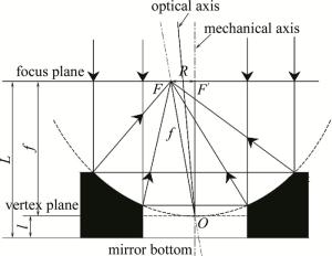
    Figure 2.  Schematic diagram of the apex of the parabola and the bottom surface of the mirror not overlapping

    在一些系统中,会用到光轴和机械轴存在夹角的抛物面反射镜[16],即反射镜的机械轴和光轴存在夹角,就需要对夹角大小进行测量,检测抛物面反射镜是否符合要求,如图 3所示。假设机械轴和光轴之间的夹角为θ,此时平行光的方向平行于机械轴,照射到抛物面反射镜上,平行光会聚在焦平面上,但是偏离光轴和机械轴,此时焦点和抛物面顶点所在的直线与机械轴之间的夹角,利用几何光学原理,可计算得到(2)式,即焦点和抛物面顶点所在的直线与机械轴之间的夹角和机械轴与光轴之间的夹角成两倍的关系。通过计算出焦点和抛物面顶点所在的直线与机械轴之间的夹角,反推出机械轴与光轴之间的夹角,实现对机械轴与光轴之间夹角的测量。

    Figure 3.  A schematic diagram of a parabolic mirror with an angle between the optical axis and the mechanical axis

    如何求出焦点和抛物面顶点所在的直线与机械轴之间的夹角是系统设计的关键,本文中提出了一种方法,通过反射镜绕着机械轴旋转,如图 4所示。由于光轴和机械轴不重合,抛物面反射镜聚焦的光斑在机械轴外,通过转动反射镜,聚焦点会绕着机械轴旋转,形成一个以机械轴为圆心,聚焦光斑到机械轴的距离R为半径的圆[17]

    Figure 4.  Schematic diagram of mirror rotation

    在焦平面出放置相机,随着反射镜的旋转,可以采集一系列的光斑图像,通过计算各光斑中心和光斑中心的空间位置,利用最小二乘法,拟合得到圆的轨迹并计算出半径R,从而求出聚焦光斑到机械轴的距离R,通过几何关系可以得到反射镜机械轴和光轴的夹角,在图 2中,平行于机械轴的平行光经过反射镜聚焦形成的焦点F,焦平面与机械轴的交F′,以及抛物面的顶点O,3个点形成一个三角形,其中FF′=ROF=f,利用几何关系,可以求出:

    式中,R为聚焦光斑到机械轴的距离,可以通过拟合圆求出,f为抛物面反射镜的焦距,在测量弥散斑的过程中可以求出。

    在实际测量过程中,很难控制平行光和机械轴平行,因此平行光和机械轴不平行会引入较大的测量误差。本文中提出了一种消除误差的方法,即一个抛物面反射镜在完成测量之后,旋转180°放置在旋转台上再次进行测量,两个结果相加取平均值,减小误差。如图 5a所示,光轴与机械轴夹角为θ,平行光与机械轴夹角为γ,平行光方向和光轴在机械轴的同侧,此时反射镜对平行光聚焦的焦点落在图示“焦点方向”的直线上,焦点方向的直线与机械轴的夹角为(2θ-γ), 反射镜旋转形成的轨迹拟合得到的圆的半径R1为:

    Figure 5.  Schematic diagram of eliminting parallel light errors

    当反射镜旋转180°,如图 5b所示,光轴和平行光方向分列机械轴两侧,此时焦点方向的直线与机械轴的夹角为(2θ+γ), 反射镜自转形成的圆的半径R2

    R1R2取平均:

    结合(3)式~(6)式,从而得到:

2.   系统设计
  • 根据测量要求,系统设计主要分为平行光光源、移动台、旋转台、相机和计算机5个部分。系统设计示意图如图 6所示。

    Figure 6.  Schematic diagram of system design

    平行光管产生平行光经过45°反射镜的反射照射到抛物面反射镜上;相机部分用来采集光斑图像;计算机用来处理光斑图像,求出弥散斑重心和抛物镜焦距并进行相关的数据处理计算,移动台配有光栅尺,可记录位置参量,精度达到5μm,通过沿y方向平移移动台控制平行光管、反射镜及相机一起移动至聚焦光斑最小位置,完成弥散斑的采集和焦距的测量;旋转台可以控制抛物面反射镜旋转,结合相机采集的光斑图片和计算机对数据的处理,从而测量得到抛物面反射镜光轴和机械轴的夹角。

3.   试验验证
  • 采用一组标准的环形抛物面反射镜验证测量系统,这组标准抛物面反射镜规格一样,焦距均为41.875mm,光轴与机械轴之间的夹角18′50″,即0.314°。

    在旋转台上放置标准的抛物面反射镜,移动移动台,采集焦点附近的一系列的光斑图像,如图 7所示。采集图像的位置距离抛物面顶点的距离为d,单位为mm。通过观察,可明显看出,在采集位置逐渐靠近焦点处时,光斑由环形逐渐聚焦为一个斑,越靠近焦点处,光斑半径越小,光斑越亮。

    Figure 7.  Spot images with different distances between the acquisition position and the vertex of the parabola

    通过对图 7中形成的圆形光斑进行图像处理,求出光斑半径大小,对每个光斑的位置和光斑大小进行拟合,得到光斑最小的位置,即焦距,再将移动台移动到最小位置处,采集图像,得到焦点处弥散斑,如图 8中的图像数据,弥散斑半径最小的位置为41.860mm,即反射镜的焦距为41.860mm,此时得到焦距位置的弥散斑大小为0.363mm。

    Figure 8.  Image of diffuse spot at focal point

    旋转旋转台,抛物面反射镜绕着机械轴以45°步进旋转,一周采集得到8张图像,将抛物面旋转180°,再次放置在旋转台上采集8张图像,如图 9所示。通过拟合光斑运动轨迹,得到半径R1=0.375mm和R2=0.532mm的两个圆,利用(6)式计算得到θ=0.311°。

    Figure 9.  Image of fitting circle with redius R1 and R2

    通过实验测量其它的标准抛物面反射镜,测量数据如表 1所示。

    number focal length/mm diffuse spot radius/mm R1/mm R2/mm R/mm θ/(°)
    1 41.860 0.181 0.375 0.532 0.454 0.311
    2 41.868 0.176 0.395 0.506 0.451 0.309
    3 41.865 0.178 0.380 0.575 0.468 0.320
    4 41.885 0.180 0.347 0.560 0.490 0.335
    5 41.882 0.176 0.383 0.609 0.449 0.307
    6 41.873 0.181 0.302 0.596 0.442 0.302
    7 41.879 0.178 0.398 0.509 0.454 0.311
    theoretical 41.875 < 0.2 0.459 0.459 0.459 0.314
    data
    maximum 0.015 0.031 0.021
    error
    error rate/% 0.03 6.7 6.6

    Table 1.  Measurement data and results

    分析测量数据可知,该测量系统的焦距测量,相对误差为0.03%;测量的弥散斑半径大小也符合测量要求,抛物面反射镜光轴和机械轴的夹角相对误差为6.6%,认为测量结果正确,符合测量要求。

4.   结论
  • 抛物面反射镜因为具有良好的光学性能,应用范围非常广泛,测量这类反射镜的光学性能非常重要,本文中提供了一种结构简单的系统,用来测量非球面反射镜的焦距、弥散斑、光轴与机械轴偏角,并且提供了一种消除由平行光带来的误差的方法,焦距误差可以控制在0.1%以内,偏角误差可以控制在7%以内。该系统精度高、结构简单、测量快、操作要求简单,为其它小口径的非球面的检测提供了很好的思路。

Reference (17)

Catalog

    /

    DownLoad:  Full-Size Img  PowerPoint
    Return
    Return