Advanced Search

ISSN1001-3806 CN51-1125/TN Map

Volume 46 Issue 1
Jan.  2022
Article Contents
Turn off MathJax

Citation:

Laser welding process of body galvanized sheet based on exhaust passage

  • Corresponding author: WEI Xin, weixin@gdut.edu.cn
  • Received Date: 2021-01-24
    Accepted Date: 2021-03-11
  • In order to solve the problem of laser laminated lap welding of galvanized sheet for automobile body, a process of rolling a certain exhaust passage on the laminated joint surface of galvanized sheet was put forward, so that a better welding effect could be obtained under zero clearance. The welding quality of zero-gap laminated joints with and without exhaust channels was compared and analyzed from the aspects of weld surface morphology, splash generation, weld microstructure, micro-hardness, and mechanical properties of joints. The results show that the composite exhaust channel with the main exhaust channel depth of 125.0μm and the secondary exhaust channel depth of 32.6μm can be obtained by rolling, and the lap joint with satisfactory appearance and mechanical properties can be obtained at laser power of 2500W and scanning speed of 25mm/s. The research is helpful to improve the laser overlay welding process of body galvanized sheet.
  • 加载中
  • [1]

    XU Z H. Experimental study on robot laser welding of galvanized sheet of automobile body in white[D]. Zhenjiang: Jiangsu University, 2010: 32-37(in Chinese).
    [2]

    BURNS T. Weldability of a dual-phase sheet steel by the gas metal arc welding process[D]. Waterloo, Canada: the University of Waterloo, 2009: 12-17.
    [3]

    SHAO J, YAN Y. Review of techniques for on-line monitoring and inspection of laser welding[J]. Journal of Physics Conference, 2005, 15(1): 101-107.
    [4]

    WANG P, CHEN X, PAN Q, et al. Laser welding dissimilar materials of aluminum to steel: An overview[J]. International Journal of Advanced Manufacturing Technology, 2016, 87(9-12): 1-10.
    [5]

    HUANG L, CHEN X Zh, MA H B, et al. Laser welding properties and process of DP780 galvanized steel[J]. Journal of Welding, 2018, 39(8): 55-58 (in Chinese).
    [6]

    CHEN W, ACKERSON P, MOLIAN P. CO2 laser welding of galvanized steel sheets using vent holes[J]. Materials & Design, 2009, 30(2): 245-251.
    [7]

    CHEN Z, YANG S, WANG C, et al. A study of fiber laser welding of galvanized steel using a suction method[J]. Journal of Materials Processing Technology, 2014, 214(7): 1456- 1465. doi: 10.1016/j.jmatprotec.2014.02.013
    [8]

    MA J, KONG F, CARLSON B, et al. Two-pass laser welding of galvanized high-strength dual-phase steel for a zero-gap lap joint confi-guration[J]. Journal of Materials Processing Technology, 2013, 213(3): 495-507. doi: 10.1016/j.jmatprotec.2012.10.019
    [9]

    SCHMIDT M, OTTO A, GELER C. Analysis of YAG laser lap-welding of zinc coated steel sheets[J]. CIRP Annals-Manufacturing Technology, 2008, 57(1): 213-216. doi: 10.1016/j.cirp.2008.03.043
    [10]

    DENG S J, WANG H P, LU F G, et al. Investigation of spatter occurrence in remote laser spiral welding of zinc-coated steels[J]. International Journal of Heat and Mass Transfer, 2019, 140: 269-280. doi: 10.1016/j.ijheatmasstransfer.2019.06.009
    [11]

    MA J, KONG F, KOVACEVIC R. Finite-element thermal analysis of laser welding of galvanized high-strength steel in a zero-gap lap joint configuration and its experimental verification[J]. Materials & design, 2012, 36(4): 348-358.
    [12]

    HUANG H J. Study on laser welding technology of automotive galvanized steel plate to reduce the influence of galvanized layer[C]//Proceedings of 2005 Annual Conference of Shanghai Laser Society. Shanghai: Shanghai Laser Society, 2005: 4 (in Chinese).
    [13]

    BLEY H, WEYAND L, LUFT A. An alternative approach for the cost-efficient laser welding of zinc-coated sheet metal[J]. CIRP Annals-Manufacturing Technology, 2007, 56(1): 17-20. doi: 10.1016/j.cirp.2007.05.006
    [14]

    HONG K M, SHIN Y C. Prospects of laser welding technology in the automotive industry: A review[J]. Journal of Materials Processing Technology, 2017, 245: 46-69. doi: 10.1016/j.jmatprotec.2017.02.008
    [15]

    LU F, LU B, TANG X, et al. Study of influencing factors and joint performance of laser brazing on zinc-coated steel plate[J]. The International Journal of Advanced Manufacturing Technology, 2008, 37(9-10): 961-965. doi: 10.1007/s00170-007-1035-7
    [16]

    ZHANG Q, LI Sh Ch, JIN X Zh, et al. Research on key technology of laser welding of galvanized steel plate[J]. Lasers & Optoelectronics Progress, 2010, 47(7): 071401(in Chinese).
    [17]

    CHEN Sh Q. Study on process rule and mechanism of laser welding of 304 stainless steel plate[D]. Guangzhou: Guangdong University of Technology, 2019: 54-59(in Chinese).
    [18]

    CHEN Zh Ch, YANG S L, WANG Ch M, et al. Study on zero-gap fiber laser lap welding of galvanized steel plate[J]. Applied of Laser, 2013, 33(5): 498-504(in Chinese). doi: 10.3788/AL20133305.0498
    [19]

    HOU Y X, LUO Z Y, YI Y Y, et al. Study on weld forming and microstructure properties of A7N01 aluminum alloy by laser-MIG composite welding[J]. Laser Technology, 2020, 44(3): 304-309(in Chinese).
    [20]

    LIANG W, FENG B, ZHU G M, et al. Laser welding properties of 1800MPa hot formed steel and Cr340La low alloy high strength steel[J]. Journal of Engineering Sciences, 2020, 42(6): 755-762(in Chinese).
  • 加载中
通讯作者: 陈斌, bchen63@163.com
  • 1. 

    沈阳化工大学材料科学与工程学院 沈阳 110142

  1. 本站搜索
  2. 百度学术搜索
  3. 万方数据库搜索
  4. CNKI搜索

Figures(9) / Tables(2)

Article views(3339) PDF downloads(18) Cited by()

Proportional views

Laser welding process of body galvanized sheet based on exhaust passage

    Corresponding author: WEI Xin, weixin@gdut.edu.cn
  • 1. School of Mechanical and Electrical Engineering, Guangdong University of Technology, Guangzhou 510006, China
  • 2. Synergy Innovation Institute for Modern Industries of Dongyuan and GDUT, Heyuan 517500, China

Abstract: In order to solve the problem of laser laminated lap welding of galvanized sheet for automobile body, a process of rolling a certain exhaust passage on the laminated joint surface of galvanized sheet was put forward, so that a better welding effect could be obtained under zero clearance. The welding quality of zero-gap laminated joints with and without exhaust channels was compared and analyzed from the aspects of weld surface morphology, splash generation, weld microstructure, micro-hardness, and mechanical properties of joints. The results show that the composite exhaust channel with the main exhaust channel depth of 125.0μm and the secondary exhaust channel depth of 32.6μm can be obtained by rolling, and the lap joint with satisfactory appearance and mechanical properties can be obtained at laser power of 2500W and scanning speed of 25mm/s. The research is helpful to improve the laser overlay welding process of body galvanized sheet.

引言
  • 镀锌钢因其优良的耐腐蚀性能,广泛应用于汽车车身等部件的制造过程中[1-3]。这得益于镀层锌对钢基体具有物理屏蔽作用的同时,还起到了电化学保护作用[4]。然而,镀锌钢的镀层结构和锌元素的物理特性(镀层锌的沸点是908℃,基体钢的熔点是300℃[5])带来了一定的工艺问题,镀锌钢在激光焊接过程中,镀层锌会剧烈气化形成锌蒸气,在熔池中造成飞溅、气孔等焊接缺陷,严重影响焊缝外观及连接强度[6]

    镀锌板在层叠搭接焊工艺下的锌蒸气行为可分为两种,上下表面的外层锌气化和层叠面处夹层锌的气化[7]。外层锌气化而产生的锌蒸气向空气中自由扩散,对焊接质量无直接影响。夹层锌蒸气的逃逸行为是引起焊接缺陷的主要因素[8]。零间隙焊接下,SCHMIDT等人[9]通过高速摄像机记录观察锌蒸气逃逸过程,发现锌蒸气通常在匙孔壁后面约1mm~4mm范围内产生脱气通道。锌蒸气的高动态压力使熔池极不稳定,导致井喷式的飞溅和孔隙[10-11]。目前较好的解决办法是板间间隙法[12-13],在搭接面间留出一定间隙, 以便夹层锌产生的锌蒸气顺利排出。通过在板间预夹薄层垫片,通过控制搭接板间的夹紧力控制板间间隙。虽然这种预留间隙的焊接方法在镀锌钢激光焊接时可以很好地排出锌蒸气,减少焊接气孔,但此方法对预留间隙的间隙值的精度要求较高,对夹具要求较高,不易控制[14-16]

    作者针对零间隙下镀锌钢的激光层叠搭接焊工艺,尝试通过在层叠搭接面设计一定的排气通道结构,控制焊接过程中锌蒸气逃逸行为,达到改善焊接接头质量的作用。

1.   实验材料与方法
  • 实验材料选用1.5mm厚的CR340冷轧热镀锌钢板,镀层为双面镀锌,镀锌量为60g/m2。钢板化学成分如表 1所示,力学性能如表 2所示,图 1为CR340基体组织金相图。实验前用激光切割制成120mm×60mm×1.5mm的试板,并用酒精擦除材料表面油污[17]

    C Si Mn Nb P S Al Fe
    0.0012 0.0015 0.005 0.00015 0.00035 0.00025 0.00015 balance

    Table 1.  Chemical composition of CR340 sheet(mass fraction)

    yield strength/MPa tensile strength/MPa elongation after fracture/%
    270 400 11

    Table 2.  Mechanical properties of CR340 sheet

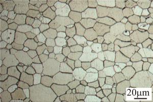
    Figure 1.  Matrix microstructure of CR340 sheet

  • 利用模数为1.0mm的右斜30°直纹滚花刀在层叠接合面处,对上下镀锌板分别辊压出交错排布的排气通道,并利用OLS4000激光共聚焦显微镜观察并测量排气通道的3维形貌。可以发现,在压力作用下,刀齿在镀锌板表面挤压出一道道主排气通道,并在主排气通道的两边形成隆起,于是在主排气通道与主排气通道之间由隆起堆叠出的微小空间形成次排气通道;由主排气通道和次排气通道形成的复合排气通道在焊缝中心实现了排气通道的全覆盖。通过控制辊压力的大小来控制辊压深度,实验前测量主、次排气通道的深度。图 2为排气通道。其中,图 2a为位置示意图,图 2b为实际辊压效果,图 2c为局部放大,图 2d为表面3维形貌,图 2e为截面形状,图 2f为主、次排气通道。

    Figure 2.  Exhaust passage

    实验中采用零间隙层叠搭接焊接头形式,重叠宽度10mm,预先在层叠面处辊压一定结构的排气通道,焊缝轨迹位于重叠面中心位置,如图 3所示。实验中用到的激光焊接系统,包括由中国武汉锐科生产的RFL-C3300型光纤激光器,波长为1080nm,经聚焦直径为200nm焊接头聚焦后得到直径为0.3mm的激光光斑。焊接时,工件固定装夹,由FANUC M-20iA六轴机械手带动焊接头运动来完成焊接。焊接完成后并对焊缝宏观形貌、飞溅情况、接头微观组织及力学性能进行分析研究。

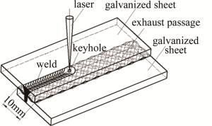
    Figure 3.  Schematic diagram of cascade lap welding

    在金相试样制取中,沿垂直于焊缝的方向截取试样尺寸为20mm×15mm×3mm的试样,按照标准金相制作方法依次进行打磨、抛光,制取金相样件,腐蚀液选择硝酸酒精溶液(质量分数为0.04),腐蚀时间为15s左右[18]。利用Leica DMC4500金相显微镜对制得的金相样件进行观察;利用HV-1000Z型显微硬度计测量焊接接头显微硬度,加载载荷和加载时间分别25g和10s。

    参照GB/T2651-2008《焊接接头拉伸试验》标准, 利用线切割制做拉伸试样[19],采用WDW3100型电子万能实验机进行拉伸测试,同参量下样件拉伸3次取平均值。

2.   实验结果与分析
  • 实验前测得主排气通道深度为125.0μm,次排气通道深度32.6μm,间隔为1mm。实验中选用的工艺参量如下:激光功率为2500W,扫描速率为25mm/s,氮气保护气流量为5L/min,保护方式为同轴保护,离焦量为0mm。由图 4中焊缝形貌的对比可看出,1#无排气通道试样、无排气通道下,焊缝成形较差,伴随着有大量的飞溅,焊缝表面凹凸不平,过渡不均匀,由于飞溅损失了熔池金属,焊缝正反面都出现不同程度的凹陷,焊缝正面存在焊瘤。2#有排气通道试样、有排气通道下,焊缝成形良好,基本无气孔、飞溅、凹坑等缺陷,焊缝表面连续均匀过渡。

    Figure 4.  The contrast of weld appearance with or without exhaust passage

  • 比较图 5中无排气管道(见图 5a)和有排气通道(见图 5b)的焊缝截面可以发现,无排气通道时,焊缝正面塌陷严重,焊缝背面轻微塌陷,熔池中存在气孔缺陷,该气孔呈椭球型,位于中间层叠面附近。有排气通道的焊缝成型良好,熔合区金属饱满,除底部有少量驼峰外,焊缝内部无其它缺陷。从熔合区与排气通道交界区域的局部放大图来看,熔池冷却后部分排气通道区域会被填充,但仅局限在熔合区。熔合区金属在与排气通道相交区域呈锥形的放射状,这是由于锌蒸气从排气通道逃逸后造成的压力差所致,这说明排气通道起到了很好的逃逸锌蒸气的作用。图 5c为熔合区与排气通道交界区域的局部放大图。图 5中, BM(base matal)为母材区,HAZ(heating affective zone)为热影响区,WZ(welding zone)为焊缝区。

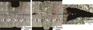
    Figure 5.  Weld section

    在焊接过程中,主、次排气通道结构为层叠面处的高压锌蒸气提供了一个缓冲、释放的路径,不至于高压的锌蒸气瞬间涌入熔池,从匙孔或者熔池上下表面逃逸,并以飞溅的形式带走大量熔池金属,同时在熔池中形成紊流。部分锌蒸气气泡未能及时释放最终在焊缝中形成气孔。

  • 利用光学显微镜在上板距层叠面0.5mm(即图 5AB线位置)与热影响区相交附近,通过拼接的方式,观察从焊缝区到热影响区,再到母材区的组织变化,如图 6所示。其中,图 6a无排气通道,图 6b有排气通道。接头组织具有明显的低碳钢焊接接头变化特性,从左至右分为峰值温度在1500℃以上的焊缝区、1500℃~1100℃的过热区、1100℃~900℃的正火区、900℃以下的部分相变及母材区。图 7则为焊缝中心熔合区组织金相图,焊缝区组织为白色块状铁素体、网状珠光体与晶界处少量的Fe3C[20](下标Ⅲ表三次渗碳体)。

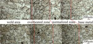
    Figure 6.  Tissue change diagram of heat affected zone

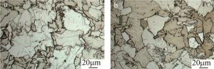
    Figure 7.  Metallographic diagram of fusion zone

    从焊缝区到母材区,无排气通道条件下,组织晶粒大小变化更为明显,且热影响区的宽度要小于有排气通道情况下。这是因为有排气通道情况下,能量传导不光通过金属本身的热传导,还有高温高压的锌蒸气通过排气通道逃逸时,以热对流的形式将部分热量传递给热影响区,使得热影响区组织晶粒过渡更为平缓。
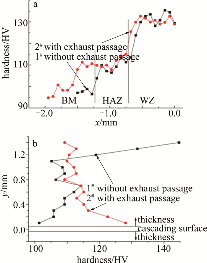
  • 图 5所示的AB线(垂直于板厚方向)及CD线(板厚方向)位置,从焊缝中心开始,向外每间隔0.075mm取样打点,测量硬度,并绘制硬度变化曲线,如图 8所示。由图 8a可见,硬度最高的是焊缝区,约为135HV,热影响区约为110HV,均大于母材区,并且没有明显的软化现象。有、无排气通道情况下,各区之间的平均硬度大致一致,但是有排气通情况下,焊缝热影响区宽度更宽。排气通道的作用是有效逃逸锌蒸气,最终起到稳定熔池、减少飞溅的作用。稳定的熔池减少了由于飞溅损失的金属液滴。因此,相同的激光工艺参量下,这部分热量可以通过母材传播更远,使得热影响区更宽。

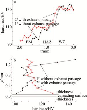
    Figure 8.  Microhardness curve

    CD线方向(板厚方向)(见图 8b)来看,无排气通道样件上板的上表面硬度有一个激增,在靠近层叠面处有一定下降。而有排气通道样件的硬度在板厚方向较为均匀,在层叠面附近有一定增长,这是因为辊压变形在层叠面处造成的应力集中,形成一层强化层。

  • 根据GB/T2651-2008焊接接头拉伸试验方法,制作拉伸试样。如图 9所示,两组实验试样断裂位置不同,2#有排气通道样件断裂在母材区,而1#无排气通道样件则在焊缝区断裂,2#应力应变曲线为典型的塑性金属拉伸曲线,分为弹性变形、屈服变形, 颈缩断裂阶段最大抗拉强度约为370MPa;1#的最大抗拉强度约为245MPa。这是由于无排气通道情况下,锌蒸气从连接件的上、下表面逃逸,过程中带走大量熔池金属液滴,形成飞溅,部分未及时逃逸的锌蒸气在焊缝区形成气孔,飞溅损失的熔合区金属和内部气孔缺陷都极大削弱焊缝的连接强度。排气通道在改善焊接质量的同时,残余部分排气通道结构并不会影响焊缝的连接强度。图 9展示了焊接头的拉伸强度。图 9a为拉伸制样尺寸,图 9b为拉剪示意图,图 9c为断裂位置图,图 9d为拉伸应力应变曲线图。

    Figure 9.  Tensile strength

3.   结论
  • 本文中提出的基于排气通道的车身镀锌板激光叠焊工艺可获得一个较好的焊接效果。焊接1.5mm厚的镀锌板焊缝基本无气孔、飞溅、凹坑等缺陷,焊缝表面连续均匀过渡。排气通道的作用是给高压锌蒸气提供一个缓冲、释放的路径,有效逃逸锌蒸气,最终起到稳定熔池、减少飞溅的作用。

    从接头拉伸结果可以发现,辊压了排气通道的层叠搭接接头强度高、接头质量可靠, 但采用排气通道工艺的镀锌板激光焊接机理有待进一步论证与认识; 对于排气通道辊压参量的优化也需要进一步研究。

Reference (20)

Catalog

    /

    DownLoad:  Full-Size Img  PowerPoint
    Return
    Return