Advanced Search

ISSN1001-3806 CN51-1125/TN Map

Volume 46 Issue 3
May  2022
Article Contents
Turn off MathJax

Citation:

Analysis of driving circuit characteristics of high-power pulsed xenon lamp

  • Received Date: 2021-04-01
    Accepted Date: 2021-04-26
  • In order to enhance the driving efficiency of high-energy pulsed laser and optimize the engineering realization effect of the driving circuit, the theoretical analysis and simulation verification of the discharge characteristics of the pulsed xenon lamp and the pulse-forming network were carried out by means of circuit analysis and simulation, and the correlation data between the influencing factors and the pulse current waveform were obtained. The results show that both the rectangularity of the pulse current waveform and the difficulty of engineering implementation increases with the number of nodes incresaing. The ideal number of nodes is about 5, and the peak amplitude decreases with the decrease of the final chain inductance, and the ideal value of the weighted value is about 0.8. The rising speed decreases with the increase of the leading inductance, and the ideal value range of the weighted value is 1.2~1.4. This research is beneficial to further promote the engineering application and development of the driving circuit of high energy pulse xenon lamp.
  • 加载中
  • [1]

    YAN J X. Laser weapons [M]. Beijing: National Defense Industry Press, 2016: 29-30(in Chinese).
    [2]

    XU J, LIANG M, LIU D Sh, et al. Research on power factor correction technology of pulse laser system charging power supply[J]. Laser Technology, 2020, 44(6): 732-737(in Chinese).
    [3]

    LI B, LI B T, HUANG B, et al. Design of high reliability pulse xe-non lamp power supply[J]. High Power Laser and Particle Beams, 2017, 29(6): 065004(in Chinese).
    [4]

    KIM K. Time-dependent one-dimensional modeling of pulsed plasma discharge in a capillary plasma device[J]. IEEE Transactions on Plasma Science, 2003, 31(4): 729-735. doi: 10.1109/TPS.2003.815472
    [5]

    LIU F C, ZHAO X J, HE S Ch. Design and experimental analysis of DSP-based PFN trigger timing control system[J]. High Voltage Engineering, 2013, 39(7): 1778-1783(in Chinese).
    [6]

    LIU F C, ZHAO X J, HE S Ch. The design of a DSP-based PFN tri-gger timing control system and the experimental study[C]//16th International Symposium on Electromagnetic Launch Technology (EML). New York, USA: IEEE, 2012: 1-6.
    [7]

    CHANG D I, LONG B, CHIU D, et al. A pulse forming network and test fixture for screening electrothermal chemical candidate propellants[J]. IEEE Transactions on Magnetics, 1993, 29(1): 919-922. doi: 10.1109/20.195700
    [8]

    LI Zh Q, YANG J H, ZHANG J D, et al. A compact repetitive PFN-marx generator[J]. High Power Laser and Particle Beams, 2016, 28(1): 015013(in Chinese).
    [9]

    TIAN J Ch, SONG X Q, LI Z L. Theoretical analysis and calculation of HPM pulse forming network[J]. Journal of Spacecraft TT&C Technology, 2003, 22(3): 72-74(in Chinese).
    [10]

    WANG Ch W, LI H T. Theoretical analysis and design of the trapezoidal pulse forming network[J]. High Power Laser and Particle Beams, 2018, 30(3): 035005(in Chinese).
    [11]

    TANG Y L, LIU J, LI B M. Research on discharge timing control of multi-parameter pulse forming network[J]. Journal of Physics: Conference Series, 2021, 1721(1): 012043. doi: 10.1088/1742-6596/1721/1/012043
    [12]

    SCHOLFIELD D W, BUTCHER M D, HILKO B, et al. Vacuum switch performance in a 1.2MJ pulse forming network[J]. The Review of Scientific Instruments, 2008, 79(1/2): 024703.
    [13]

    LI X Q, ZHAO J, WU H G, et al. Design of xenon flash lamp su-pply adopting integrally triggering and pre-ionization[J]. High Power Laser Particle Beams, 2014, 26(7): 075004(in Chinese). doi: 10.3788/HPLPB20142607.75004
    [14]

    CAO Sh G, SHAO R Y, LIN W Zh, et al. Study on the dynamic model of high power flash lamp for simulation with Pspice. A-pplied Laser, 2006, 26(6): 457-459(in Chinese).
    [15]

    ZHAO Y Q, DONG P F, MIAO P L, et al. Study on discharge process of high performance xeon flash lamp[J]. Analytical Instrumentation, 2016, 206(4): 44-48(in Chinese).
    [16]

    WANG Ch W, LI H T. Design of trapezoidal pulse forming network based on simplex optimization method [J]. High Power Laser and Particle Beams, 2020, 32(6): 065001(in Chinese).
    [17]

    LIN Q H, LI B M. Analysis on surge process generated in high power pulse forming network with capacitor energy storage system[J]. Journal of Nanjing University of Science and Technology, 2008, 32(6): 729-732(in Chinese).
    [18]

    KOECHNER W S. Solid-state laser engineering[M]. Beijing: Science Press, 2002: 257-267(in Chinese).
    [19]

    CHEN D G. Some problem in design of design of pulse forming network[J]. Modern Electronics, 1998, 63(2): 22-27(in Chinese).
    [20]

    ZHAO J, LI B T, WANG Ch W, et al. Design of pulsed power circuit based on waveform analysis[J]. High Power Laser and Particle Beams, 2017, 29(12): 065004(in Chinese).
    [21]

    LONG X F. Investigation of marx-PFN[D]. Changsha: National University of Defense Technology, 2007: 5-21(in Chinese).
    [22]

    LIU X S. High pulsed power technology[M]. Beijing: National Defense Industry Press, 2005: 116-119(in Chinese).
    [23]

    ZHOU T M. Principle design of light source[M]. Shanghai: Fudan University Press, 2006: 387-391(in Chinese).
    [24]

    YU Y J, FAN P Zh, FANG W G. Measurement of electrode drop of pulsed xenon lamp[J]. Laser Journal, 1979, 6(5): 41-44(in Chinese).
  • 加载中
通讯作者: 陈斌, bchen63@163.com
  • 1. 

    沈阳化工大学材料科学与工程学院 沈阳 110142

  1. 本站搜索
  2. 百度学术搜索
  3. 万方数据库搜索
  4. CNKI搜索

Figures(6) / Tables(5)

Article views(3356) PDF downloads(19) Cited by()

Proportional views

Analysis of driving circuit characteristics of high-power pulsed xenon lamp

  • Southwest Institute of Technical Physics, Chengdu 610041, China

Abstract: In order to enhance the driving efficiency of high-energy pulsed laser and optimize the engineering realization effect of the driving circuit, the theoretical analysis and simulation verification of the discharge characteristics of the pulsed xenon lamp and the pulse-forming network were carried out by means of circuit analysis and simulation, and the correlation data between the influencing factors and the pulse current waveform were obtained. The results show that both the rectangularity of the pulse current waveform and the difficulty of engineering implementation increases with the number of nodes incresaing. The ideal number of nodes is about 5, and the peak amplitude decreases with the decrease of the final chain inductance, and the ideal value of the weighted value is about 0.8. The rising speed decreases with the increase of the leading inductance, and the ideal value range of the weighted value is 1.2~1.4. This research is beneficial to further promote the engineering application and development of the driving circuit of high energy pulse xenon lamp.

引言
  • 高能脉冲激光器指的是具有较大的输出功率、每间隔一定时间发出一个或多个激光脉冲(宽度通常小于250ms)的激光器,广泛应用于毁伤、焊接、烧蚀等应用场合[1-2]。高能脉冲激光器具有较高的亮度,通常采用脉冲氙灯作为激光源,其工作原理是利用储能驱动装置储存的电能对高能脉冲氙灯进行放电激发,储能驱动装置产生的近矩形的驱动电流波形可以激励脉冲氙灯获得稳定的高亮度,同时也可以精确控制脉冲氙灯的放电过程[3]。目前,国内外氙灯驱动装置主要采用脉冲成形网络(pulsed forming network, PFN)来存储初始能量,并通过调节脉冲驱动电流的波形来满足实际应用需求[4]

    近年来,LIU等人研究了PFN的波形构造和精确触发控制[5-10]; TANG等人研究了PFN电路的时序控制[11]; SCHOLFIELD等人讨论了真空状态下PFN的放电特性[12]; LI等人研究了氙灯的放电特性和建模[13-15]。尽管对PFN和脉冲氙灯已经做了大量研究工作,实践中仍然存在一些局限,如增加PFN网络节数可以有效改善波形[16],但由于重量和体积的约束,过多的网络节数可能不能接受;由于PFN放电过程短暂[17],在很多模型和分析中,氙灯的阻抗都被等效为恒定不变的阻值,而在工程设计和实际的应用中,氙灯阻抗总是随导通电流的改变而动态改变[18],且阻抗的这种变化会影响PFN放电过程和放电特性[19]。因此,建立包含这种氙灯放电特性的驱动电路模型,并将PFN和高能脉冲氙灯结合成为一个整体,结合工程化进行放电特性的研究,可以更加真实地反映驱动电路的工作特性,并且有利于进一步推动高能脉冲氙灯驱动电路的工程应用及拓展。

    本文中简述了PFN的基本原理和脉冲氙灯的放电特性,探讨了电气参数的计算,通过仿真分析了PFN节数、首末电感、网络电感等电气参数对脉冲电流波形的影响,并分析了PFN节数对工程实现的影响。

1.   基本组成
  • 本文中阐述的高能脉冲氙灯储能驱动装置由PFN线路和脉冲氙灯两部分构成。其工作原理为脉冲氙灯点火后,经充电的PFN网络对脉冲氙灯进行短时大电流放电,产生高功率、高亮度的激光。

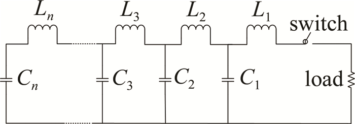
  • 脉冲成形网络是将R-L-C 3种无源器件根据一定的规则形成电路组元,利用各组元放电波形的叠加形成满足实际应用需要的电流波形[20]。PFN有3种类型:一类是根据雷利法则设计而来;另外的两种类型分别是基于导纳函数的有理分式和传输线阻抗函数展开[21]。其中雷利脉冲成形网络由多个电路拓扑结构相同的电路组元串联而成,如图 1所示。由于雷利脉冲成形网络每个电路组元的电容、电感参数一致,能实现类似方波的脉冲电流输出,且在工程应用上方便实现,使其成为脉冲功率应用领域的主要网络形式[22]

    Figure 1.  PFN circuit

    网络阻抗Z为:

    式中, L表示网络中各电感之和,C表示网络中各电容之和。

    由于放电开始时刻的电感电流为0,网络中的能量全部保存在电容中,网络中的能量为:

    式中, U是放电开始时刻电容两端的电压。

  • 脉冲氙灯由加在电极的高压于轴向形成强电场后,在触发脉冲作用下,灯管气体进入类稳放电阶段[23],此时氙灯的等离子体电阻率可用下式表示:

    式中, K1为等离子体电阻率系数;j为电流密度。

    此时脉冲氙灯电压-电流变化规律用下式描述:

    式中, VAK是电极位降;VI是氙灯瞬时电压和瞬时电流;ld是氙灯的弧长和直径。

    将(3)式代入(4)式,忽略20V左右的电极位降VAK[24],脉冲氙灯的电压-电流特性方程用下式描述:

    式中, 氙灯系数K0=2K1l/($ d\sqrt {\rm{ \mathsf{ π} }} $)。

    K0在理论上只与氙灯内的气体类型和气压有关,目前常用的经验公式首先由GONZE提出:

    式中, p为氙灯内放电前气体压强。

    脉冲氙灯的等效阻抗为:

    脉冲氙灯的放电能量为:

    式中, Tp为氙灯放电脉冲宽度,Im为平均电流。

    将(7)式代入(8)式可得:

2.   电路仿真及结果分析
  • 根据放电网络的阻抗与负载(脉冲氙灯)的阻抗匹配进行电阻参数的计算与仿真,设:

    式中, k是阻抗匹配系数。

    由于E=E, 联立(1)式、(2)式、(9)式、(10)式、(11)式可得:

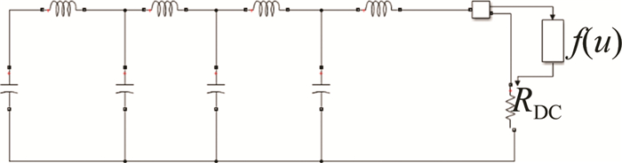
    建立电路仿真模型如图 2所示,图中f(u)是激励函数。

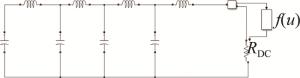
    Figure 2.  Simulation model

    以某型产品为例,计算电路参数并进行放电特性仿真。仿真中,放电能量E=10000J,氙灯放电脉冲宽度Tp=1.2ms,氙灯特性系数K0=61.38Ω·A1/2,根据阻抗匹配系数计算电路参数,如表 1所示。

    k C/μF L/μH U/V
    1.25 399.97 885.06 7071
    1 506.21 716.03 6285
    0.75 661.18 519.64 5499
    0.5 899.86 318.13 4714
    0.25 1322.24 117.14 3889

    Table 1.  Circuit parameters with different k values

    为不失一般性,设置放电网络的节数n=4,仿真结果如图 3所示。

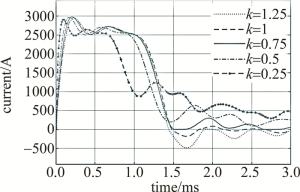
    Figure 3.  Pulse current waveform at different k values

    图 3可知,k>1时, 驱动电流会产生反向过冲现象,危害氙灯运行安全; k < 0.75时, 驱动电流下降沿会产生震荡现象,影响氙灯光电转换效率。k的理想设置区间为0.75~1。
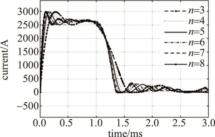
  • 对2.1节中某型产品k=0.75的情况,保持CL不变,开展不同节数n的仿真分析,设置节数n分别为3,4,5,6,7,8,网络中电容和电感均相同,仿真结果如4图所示,波形数据如表 2所示。

    n rise time/
    μs
    fall time/
    μs
    effective pulse width/μs wave crest/
    A
    3 136 518 916 2974
    4 103 405 978 2974
    5 83 352 1001 2974
    6 67 307 1021 2974
    7 58 270 1035 2974
    8 52 245 1048 2974

    Table 2.  Influence of node on discharge waveform

    图 4表 2可知,当网络节数越大时,脉冲波形前后沿越陡峭,变化速度越快,但节数从6增加到8时,脉冲前沿和后沿变化率的变化幅度远不如节数从3增加到5的大。随着节数的增多,放电电流波形中的波峰和波谷数量也越多,且数量和节数相同,而波峰和波谷的幅值依次减小。可以预见,当节数越多时,所产生的放电电流波形越接近矩形。在放电时,无论节数有多少,放电电流波形中的第1个波峰均会出现较为明显的过冲,且波峰的幅值不受节数的影响。

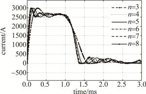
    Figure 4.  Pulse current waveform at different node

  • 对2.1节中某型产品k=0.75的情况,保持CL不变,开展不同节数n的工程实现分析,设置节数n分别为3,4,5,6,7,8,网络中电容和电感均相同,工程实现后的体积、重量和失效率如表 3所示。

    n total volume/
    cm3
    total weight/
    kg
    failure rate/
    (10-6h-1)
    3 101284 25.6 0.9370
    4 115484 31.2 1.2493
    5 133339 37.2 1.5617
    6 148436 43.0 1.8740
    7 154525 47.5 2.1864
    8 158306 51.8 2.4987

    Table 3.  Engineering parameters at different node

    在实际工程应用中,电容和电感往往采用一体化设计,经脉冲成形电路的各元件封装在一个箱体内,设计结果显示,产品的体积、重量和失效率均随着网络节数的增加而近似线性增加,其中失效率随着网络节数的增加而成比例的增加,因此,最终在确定电路结构时应考虑安装空间、重量以及任务可靠度的要求,综合考虑各约束条件来选择网络节数,以满足工程实现要求。

  • 对首链的电感值进行加权,为不失一般性,设网络节数n=4,则:

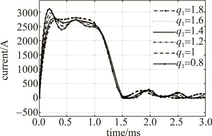
    设置首链电感加权值q1为1.8,1.6,1.4,1.2,1,0.8,仿真结果如图 5表 4所示。

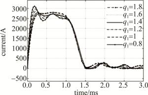
    Figure 5.  Discharge waveform with different leading chain inductance weights

    n rise time/
    μs
    fall time/
    μs
    effective pulse width/μs wave crest/
    A
    overshoot amplitude/%
    0.8 85 408 995 3102 17.37
    1 103 405 978 2974 12.52
    1.2 120 402 963 2877 8.85
    1.4 143 416 953 2782 5.26
    1.6 152 416 936 2772 4.88
    1.8 168 442 920 2746 3.40

    Table 4.  Influence of inductance weighted value of leading chain on waveform

    图 5表 4可知,首链电感的电感值改变对放电电流波形第1个波峰的影响较大,减小首链电感的电感值可使上升沿变快,但会使波峰的过冲加剧,且第1个波峰后会跟随有震荡,增大首链电感的电感值可抑制波峰的过冲,但会改变上升时间和下降时间,将首链电感加权至1.2时可明显抑制过冲,加权至1.6以上时抑制过冲不再明显,且上升时间和下降时间显著增加。因此,首链电感加权值的理想取值区间为1.2~1.4。

  • 对首链的电感值进行加权,为不失一般性,设网络节数n=4,则:

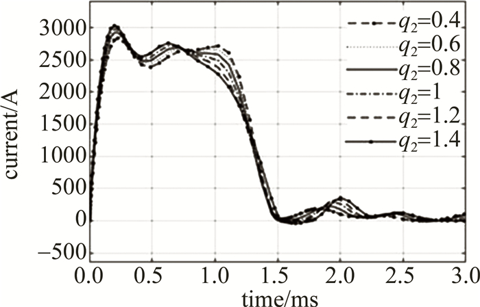
    设置末链电感加权值q2为1.4,1.2,1,0.8,0.6,0.4,仿真结果如图 6表 5所示。

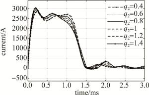
    Figure 6.  Discharge waveform with different end chain inductance weights

    n rise time/
    μs
    fall time/
    μs
    effective pulse
    width/μs
    wave
    crest/A
    overshoot
    amplitude/%
    0.4 124 322 1038 2831 7.11
    0.6 116 324 1028 2880 8.97
    0.8 109 345 1011 2924 10.63
    1 103 405 978 2974 12.52
    1.2 98 446 931 3019 14.23
    1.4 97 547 858 3028 14.57

    Table 5.  Influence of inductance weighted value of end chain on waveform

    图 6表 5可知,末链电感的电感值改变对放电电流波形第1个波峰影响较小,减小末链电感的电感值可使下降沿变宽,有效脉宽小幅度变宽,但也会小幅度增加上升时间。因此,末链电感加权值的理想取值点在0.8附近。

3.   结论
  • 本文中从工程实现的角度分析了脉冲成形网络的电路结构以及电感、电容参数计算,基于氙灯的放电特性,建立了仿真模型,通过仿真分析了影响脉冲波形的因素,并分析了电路结构对工程实现的影响程度。

    在实际设计过程中,要综合考虑性能指标要求,以及体积、重量、失效率等应用要求,来确定PFN节数,节数越多,脉冲波形越接近矩形,但同时产品的体积和重量更大,失效率更高。改变首链和末链电感值可以调节放电电流波形的波峰和波谷幅值,并可以微调前后沿波形,但波峰最高幅值和脉冲前后沿两个指标只能平衡,不可兼得,因此,在工程应用中应结合需求,综合考虑,合理调整电路中的各个参数。

Reference (24)

Catalog

    /

    DownLoad:  Full-Size Img  PowerPoint
    Return
    Return