Long guide rail alignment systems based on position sensitive detectors
-
摘要: 为了检测长导轨的直线度,采用激光作为参考基准线,将2维光斑位置传感器作为光电转换器件。当固定在导轨滑块上的2维光斑位置传感器沿着导轨移动时,光斑的位置数据会通过蓝牙模块传输到终端上,输入位置信息之后,软件会自动绘制出导轨的2维直线度曲线。结果表明,计算出激光偏角带来的误差远小于1μm;通过高精度位移平台,实验验证了系统的精度可达到3.4μm;实际使用中,检测了7.2m的长导轨,取得了长导轨的直线度数据,重复精度可达5μm。这一结果对长导轨直线度测量的研究是有帮助的。Abstract: In order to detect the long rail straightness, laser was used as the reference line, and 2-D position sensitive detector was used as photoelectric converter. When 2-D position sensitive detector was fixed on the guide rail slider and moved along the guide rail, the spot position data was transmitted to the terminal through bluetooth module. After entering the location information, the curve of 2-D straightness was drawn by the software automatically. The results show that, through theoretical analysis, the error of laser deflection angle is calculated and is less than 1μm. The system accuracy is verified by high-precision displacement platform experiment and reaches 3.4μm. In practical appliaction, a long rail of 7.2m is detected and the straightness data of long guide rail is obtained. The repeatability precision can reach 5μm. The study is helpful for straightness measurement of long rails.
-
Keywords:
- laser technique /
- laser alignment /
- contrast experiment /
- position sensitive detector
-
引言
导轨直线度[1-2]是评价机床质量的重要指标, 直接影响机床加工出来的产品精度和机床质量。在机床生产过程中,检测机床直线度并进行修正[3-5]是提升机床质量关键的环节。
导轨直线度的传统检测方法有平尺法、钢丝法等。目前国内普遍采用的通用工具如水平仪、自准直仪等[6],多是以测量元件的精度为基准, 人为引入的误差较大, 其检测精度难以满足目前工业界的需要[7]。激光具有高方向性以及高亮度等优点,非常适合作为测量的基准。使用激光作为测量基准的测量方法与传统测量方法相比,具有测量精度高、体积小、几乎不受被测导轨长度的制约等优点[8]。随着科技的发展, 直线度检测发展至自动测量[9], 其中,以图像控制器(charge-coupled device,CCD)或光斑位置传感器[10](position-sensitve device, PSD)等光电传感器为核心的激光准直技术被不断应用在直线度检测领域中[11-13],使得直线度准直精度至少提升了一个数量级[14]。本文中介绍的基于PSD的长导轨准直系统,以精度为3.4μm的PSD为接收器,测量长度为7.2m的导轨,重复精度优于5μm。
1. 工作原理
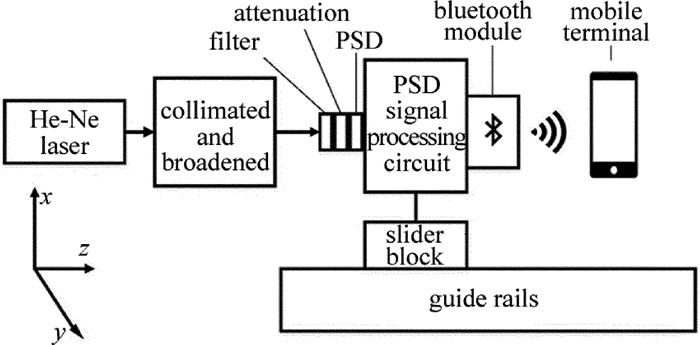
图 1为系统原理图。导轨直线度测量系统主要分为3个部分:发射模块、接收模块和处理模块。发射模块发出激光,接收模块探测激光光斑重心,并且固定在导轨滑块上随之一起运动,处理模块负责处理、展示数据。向处理模块中输入导轨的坐标后,处理模块会显示导轨的直线度偏差曲线,标出导轨不同位置的直线度偏差。
发射模块由He-Ne激光器和透镜组组成。He-Ne激光器发出激光之后,经过透镜组的准直与放大,与导轨平行地发射到接收模块上。经过处理之后的激光准直性良好[15],光斑直径不超过2mm,功率约为5mW[16-17]。
接收模块主要由红光滤光片、衰减片、PSD、PSD处理电路和蓝牙模块组成,其主要功能是检测出光斑的重心坐标并通过蓝牙模块发送给移动终端。红光滤光片的作用在于把自然光和He-Ne激光器发出的红光(632.8mm)分离。衰减片的作用在于将接收到的激光功率控制在1mW以下。PSD主要功能是检测光斑的重心位置,中心区域的检测精度可以达到3.4μm。由于PSD输出信号会受到暗电流、非线性失真等因素的负面影响,给PSD配套使用了一块处理电路板(滨松公司C9069)用于提高PSD检测的精确性。蓝牙模块用于和移动终端的远程通信。整个接收模块用铝制外壳包裹用于使用现场屏蔽电磁干扰和灰尘。
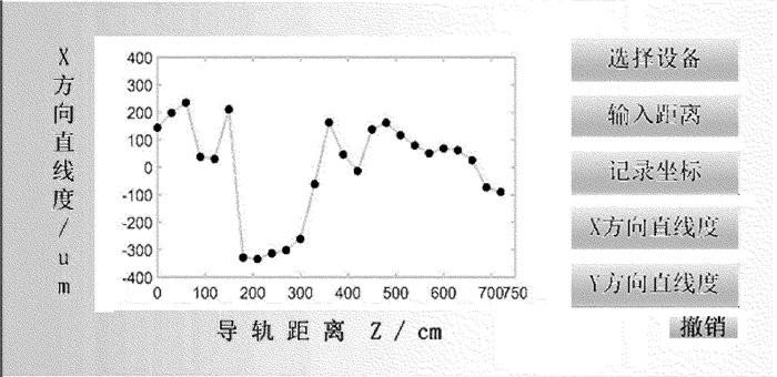
处理模块即移动终端,可以是安卓手机或者笔记本电脑。安装了为实验特制的软件之后即可接收实验数据,在输入导轨坐标之后,能够绘制导轨的直线度曲线,并标明导轨每个位置的直线度偏差,精确到5μm。图 2为手机上绘制直线度曲线的软件图。
2. 硬件设计
用Reallight公司生产的He-Ne激光器输出单模激光,功率约为5mW[18]。扩束准直分别使用焦距为8mm以及200mm的凸面镜,80mm镜片焦点处放置直径为0.1mm的小孔进行空间滤波。滤波后激光准直性和单色性得到增强。
接收模块核心部件PSD为日本滨松公司生产的S1880型2维位置传感器,光斑重心测量精度为3.4μm。PSD安装在C9069型电路板上,PSD接收光斑后输出光斑的重心坐标给电路板,由于PSD本身的枕形结构[19],电路板使用特定的算法[20-21]修正了这一结构带来的误差[22]。输出接口为RS232串行接口, 接上蓝牙模块即可在30m内进行数据的无线传输。
3. 验证实验
3.1 关于PSD倾斜带来的误差分析
从图 1中可以看出,接收模块的核心部件PSD是固定在滑块上的,PSD始终垂直于导轨,而导轨并不是完美的直线,存在着左右与上下的起伏,因此随着滑块在导轨上的滑动,PSD和激光不再是垂直的关系,两者之间存在一个偏角α, 这个偏角会对PSD测量的坐标产生影响[23]。
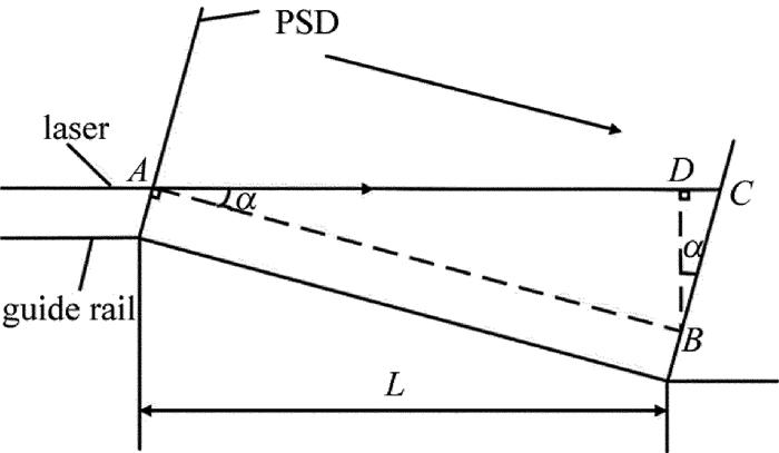
图 3为激光偏角的原理图。其中直线AC代表激光,A点是滑块移动之前激光与PSD的交点,C点是滑块移动之后激光与PSD的交点。直线AB,BD是辅助线,AB平行于导轨,BD垂直于AC。
当导轨出现倾斜时,测量系统测得的光斑位移为线段BC(设为d1),实际上的导轨偏差位移为线段BD(设为d2), 测量误差设为δ, 直线AC和直线AB之间的夹角设为α, 则有以下关系:
δ=d1−d2=d1(1−cosα) (1) 导轨在直线度测量之前都会经过普通水平尺的测量,精度为0.029°, 等于0.5mm/m,所以,α < 0.029°。另外d1(即线段BC长度)被PSD的直径限制,小于6mm。由此可以算出:
\delta < 12{\rm{mm}} \times \left( {1 - {\rm{cos}}0.029^\circ } \right) = 0.00153{\rm{ \mathsf{ μ} m}} (2) δ≪1μm, 相对于PSD的精度3.4μm来说可以忽略不计。因此, 激光偏角对直线度测量造成的误差可以忽略不计。
3.2 PSD精度验证实验
日本滨松公司给出PSD的参考精度为3.4μm。为了验证长距离情况下PSD的使用精度,采取了高精度位移平台来进行验证实验,位移平台精度达到1μm,激光器固定在距离PSD 10m处,检测装置和位移平台一起移动,读出位移平台上的数据和PSD导轨准直系统给出的位移数据,接着进行比较,观察PSD的精度,如表 1所示。
Table 1. Displacement of micro-displacement platform and PSDtheory displacement/μm actual displacement/μm deviationvalue/μm 56 54.70 1.30 43 44.40 1.40 229 232.50 3.50 107 109.45 2.45 233 235.82 2.82 115 116.35 1.35 69 71.70 2.70 232 232.50 0.50 107 106.05 0.94 59 58.10 0.90 58 61.59 3.59 120 119.60 0.40 60 61.59 1.59 59 58.10 0.90 105 105.30 0.30 从表 1中可以看出,一共15组数据,平均误差为1.64μm,最大误差为2.70μm,标准差为1.06μm,小于3.4μm。基于以上数据可以得出结论:PSD的测量精度达到了3.4μm。
3.3 导轨精度检测实验
为了检验导轨准直系统的实际使用情况,在河南某数控机床有限公司开展了现场实验,检测了还没有经过准直的机床。导轨长度为8m,由于接收模块在导轨上的滑块本身长30cm,不可以移出导轨,所以只测了7.2m的长度。每隔30cm测一个点,一共测了25组数据,重复测试了3次。
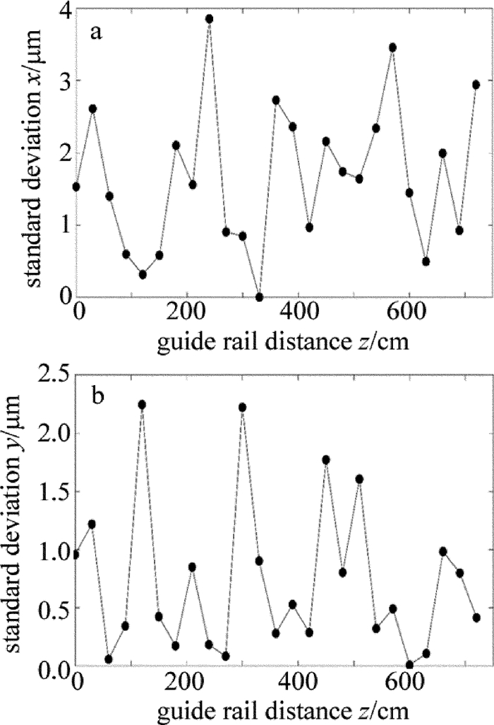
导轨在x, y方向上的直线度如图 4所示。导轨3次测量的标准差如图 5所示。
从图 4中可以看出机床导轨在x(水平)方向、y(垂直)方向上的直线度。x方向上的偏差较小,y方向上偏差较大,这是由于导轨安装的方式决定的,x方向没有螺丝固定,精度主要依赖于导轨出厂时的精度,本身不易产生偏移。y方向由螺丝固定,螺丝的松紧会造成导轨的形变,从而引起导轨的起伏,即y方向上的误差。
从图 5中可以看出,导轨x方向、y方向重复精度都小于4μm,满足5μm的精度要求。这意味着工人可以根据这些数据进行机床准直的调节,预期调节精度可以达到5μm。
4. 结论
设计出了一套安装简单、使用方便的导轨准直系统,能够满足高精度导轨直线度的测量要求。通过理论计算,排除了激光偏角的影响,通过实验验证了PSD的精度,达到了3.4μm;通过工厂的实验,证明导轨准直系统在测量7.2m长的导轨时,重复精度可以达到5μm,满足高精度导轨直线度的测量要求。
-
Table 1 Displacement of micro-displacement platform and PSD
theory displacement/μm actual displacement/μm deviationvalue/μm 56 54.70 1.30 43 44.40 1.40 229 232.50 3.50 107 109.45 2.45 233 235.82 2.82 115 116.35 1.35 69 71.70 2.70 232 232.50 0.50 107 106.05 0.94 59 58.10 0.90 58 61.59 3.59 120 119.60 0.40 60 61.59 1.59 59 58.10 0.90 105 105.30 0.30 -
[1] WANG Y P. Research of flatness and linearity testing system[D].Shenyang: Shenyang University of Technology, 2004: 9-38(in Chin-ese).
[2] YUE W L, WU Y. A fast evaluation method for flatness and straightness tolerance by means of incremental algorithm[J].Acta Metrologica Sinica, 2008, 29(2):120-123(in Chinese). http://www.wanfangdata.com.cn/details/detail.do?_type=perio&id=jlxb98200802007
[3] HUANG F G, CUI Ch C. Comparison of evaluating precision of straightness error between least square method and least envelope zone method[J].Optics and Precision Engineering, 2007, 15(6):879-893(in Chinese). http://www.wanfangdata.com.cn/details/detail.do?_type=perio&id=gxjmgc200706015
[4] LI Y J, ZHENG Z G. Calculation of straightness error and computerization[J].China Measurement Technology, 2007, 33(3):67-69(in Chinese). http://en.cnki.com.cn/article_en/cjfdtotal-sycs200703022.htm
[5] HU Zh X. Research on digitized evaluation theory and algorithm for the straightness error[D].Hunan: Hunan University, 2012: 15-94(in Chinese).
[6] SONG Q. Research on straightness measurement system of long rails based on 2D-PSD[D]. Changchun: Changchun University of Science and Technology, 2014: 2-20(in Chinese).
[7] LI F. Study on straightness testing system of super-length guideway[D]. Changchun: Changchun University of Science and Technology, 2002: 2-15(in Chinese).
[8] LÜ A M, WANG Zh X, HE A Zh, et al. Measuring the straightness of the long slideway using PSD[J].Journal of Transducer Technology, 1996(5):55-56(in Chinese). http://www.wanfangdata.com.cn/details/detail.do?_type=perio&id=QK199600895803
[9] JIA T X, XU X P, DONG W B. Design of automatic testing system for 2-D position sensitive detector(PSD)[J]. Instrument Technique and Sensor, 2012(10):67-69(in Chinese). http://www.en.cnki.com.cn/Article_en/CJFDTOTAL-YBJS201210023.htm
[10] MA Ch G, YUAN H X, HE A Zh. Research of anti-jamming in facula orientation[J]. Laser Technology, 2002, 26(4):308-310(in Chinese). http://www.wanfangdata.com.cn/details/detail.do?_type=perio&id=jgjs200204016
[11] MOU L N. Displacement detection system design based on PSD[D]. Taiyuan: North Central University, 2007: 2-30(in Chinese).
[12] LIU P, GAO L M, LE K D. Laser measurement system for rail linearity[J]. Laser Technology, 2009, 33(6):575-578(in Chinese). http://en.cnki.com.cn/Article_en/CJFDTOTAL-JGJS200906008.htm
[13] HU Ch D, LI Y Q, Zh X, et al. Laser alignment measuring and testing equipment based on interference fringe[J]. Laser Technology, 2009, 33(5):522-525(in Chinese). http://www.wanfangdata.com.cn/details/detail.do?_type=perio&id=jgjs200905030
[14] YANG Sh L, SU Y B, HE J T, et al. Study of measurement accuracy of position sensitive detectors[J]. Laser Technology, 2014, 38(6):830-834(in Chinese). http://www.en.cnki.com.cn/Article_en/CJFDTOTAL-JGJS201406023.htm
[15] FENG Q B, LIANG J W. Development of a single mode fiber laser collimator[J]. Laser Technology, 1994, 18(6):357-360(in Ch-inese). http://en.cnki.com.cn/Article_en/CJFDTotal-JGJS406.010.htm
[16] LÜ A M, YUAN H X, HE A Zh. The research in the influence of beam spot on the precision of PSD[J]. Laser Technology, 1998, 22(5):294-297(in Chinese). http://www.wanfangdata.com.cn/details/detail.do?_type=perio&id=QK199800288938
[17] LÜ A M, YUAN H X, HE A Zh. Experimental study of the effect of light source on position precision of PSD[J]. Laser Technology, 2000, 24(3):192-195(in Chinese). http://en.cnki.com.cn/Article_en/CJFDTOTAL-JGJS200003017.htm
[18] FENG Q B, ZHANG B, KUANG C F. A straightness measurement system using a single-mode fiber-coupled laser module[J]. Optics & Laser Techology, 2004, 36(4):279-283. DOI: 10.1016-j.optlastec.2003.09.016/
[19] SONG C, YENG Ch S. Linearity indices and linearity improvement of 2-D tetralateral position-sensitive detector[J]. IEEE Transactions on Electron Devices, September, 2010, 57(9):2310-2316. DOI: 10.1109/TED.2010.2051862
[20] LIU Ch, MA Y. Nonlinear correction of PSD with genetic algorithm based on neural network[J]. Journal of Electronic Measurement and Instrument, 2015, 29(8):1157-1163(in Chinese). http://www.en.cnki.com.cn/Article_en/CJFDTOTAL-DZIY201508011.htm
[21] LIN Q S, YANG X J, WANG J X, et al. 2-D nonlinear correction in an improved BP neural network[J]. Laser Technology, 2012, 36(1):124-130(in Chinese). http://en.cnki.com.cn/Article_en/CJFDTotal-JGJS201201033.htm
[22] LI Zh K, QIN Y Y. Research of on-line measurement and non-linearity correction of two dimention PSD device[J]. Laser Technology, 2004, 28(4):370-372(in Chinese). http://en.cnki.com.cn/Article_en/CJFDTOTAL-JGJS200404009.htm
[23] EKINCI O, MAYER J R R. Relationships between straightness and angular kinematic errors in machines[J]. International Journal of Machine Tools & Manufacture, 2007, 47(12/13):1997-2004. http://www.sciencedirect.com/science/article/pii/S0890695507000387
-
期刊类型引用(4)
1. 罗鹏煌,程银宝,罗哉,沈斌,江文松,李亚茹,王瑛辉. PSD几何误差测量系统及不确定度分析. 光学技术. 2024(05): 634-640 .  百度学术
百度学术
2. 李振美. 基于激光光斑定位的分布异构网络微小故障识别方法. 激光杂志. 2022(05): 171-175 .  百度学术
百度学术
3. 朱爽,王琳,高强,彭胡. 滚动导轨系统空间误差检测的正交光栅补偿. 激光杂志. 2022(09): 193-197 .  百度学术
百度学术
4. 黄战华,方石,张亚男,蔡怀宇,张尹馨. 基于位置传感器的空间激光准直系统标定技术. 激光与光电子学进展. 2018(11): 86-92 .  百度学术
百度学术
其他类型引用(3)


 下载:
下载:


