Simulation and analysis of LiDAR based on DPMZM and microwave photonic frequency multiplication
-
摘要: 为了提升调频连续波激光雷达调制带宽、从而提高距离分辨率,采用基于双平行Mach-Zehnder调制器的外调制方式,结合无光滤波器的微波光子倍频技术,通过1 GHz的射频源实现8 GHz的宽带射频调制信号,并利用搭建的模型研究了微波光子倍频子系统中消光比、调制系数和移相器相位偏移3个参数的变化对调频连续波激光雷达系统性能的影响。结果表明,大部分商用调制器的消光比可以满足使用需求,调制系数在2.385~2.425范围内或电移相器误差不大于1.3°时,该激光雷达探测信号峰的功率抑制比可以保持在20 dB以上。此研究结果为微波光子倍频技术在调频连续波激光雷达中的应用提供了理论支持,对工程实现有一定的参考意义。Abstract: In order to increase the modulation bandwidth of frequency-modulated continuous wave (FMCW) light detection and ranging (LiDAR) for the high range resolution, with the use of external modulation mode based on dual-parallel Mach-Zehnder modulator (DPMZM), combined with the microwave photonic frequency multiplication technology where no optical filters were used, the broadband radio frequency(RF) modulated signal of 8 GHz was realized from a 1 GHz RF source. Furthermore, the effect of the variation of three parameters in the subsystem, namely extinction ratio, modulation index, and phase shift of phase shifter, on the performance of the built FMCW LiDAR system model was investigated. The results show that the extinction ratio of most commercial modulators can meet the requirements of use. When the modulation index is in the range of 2.385~2.425 or the electrical phase shifter error is not greater than 1.3°, the suppressed ratio of FMCW LiDAR detection signal peak power can be maintained above 20 dB. These researches provide theoretical support for the application of microwave photonic frequency multiplication technique in FMCW LiDAR and have certain reference significance for engineering implementation.
-
引言
调频连续波(frequency-modulated continuous wave, FMCW)激光雷达(light detection and ranging, LiDAR)采用相干探测,相较于采用直接探测的脉冲式激光雷达,其信噪比高3~4个数量级,并且距离分辨率仅取决于发射信号的调制带宽[1-2],这使得FMCW激光雷达在自动驾驶、遥感测绘、3维成像等诸多领域获得了广泛的应用[3-5]。FMCW激光雷达具有内调制[6-7]和外调制[8-10]两种形式。内调制方式结构简单、调制带宽大,但由于复杂的机制难以彻底解决非线性问题,该方法对信号的调制时间较长,一般达到毫秒甚至秒量级,对系统的探测速度产生制约[11]。相比之下,外调制方式的调制过程发生在激光器外部,降低了对激光器本身和外部环境的限制条件,还能实现高扫描速率下的高线性度,但这种方案要在微波域产生高达数千兆赫兹或以上的射频驱动信号,对微波器件带宽和数模转换速率提出了过高要求,甚至难以有效工程实现,提高射频信号的带宽十分困难且成本高昂。
相比于传统雷达微波的产生方式,微波光子倍频技术提供了一条新的产生大带宽稳定微波信号的途径[12-15]。该技术的实现方式主要有直接调制法[16-17]、光外差法[18-20]、外调制法[21-22]以及包括四波混频[23-24]和受激布里渊散射法[25]在内的非线性效应法等。其中,外调制方案由于系统结构相对简单、器件发展成熟、运行稳定性好、灵活且易于实现而备受关注。其主要思路是利用电光调制器将射频电信号调制到光载波上,借助其它光电器件的非线性特性产生高阶边带,通过控制相关调制参数或结合波长选择开关及光学滤波器等装置实现对光学边带的选择,最后借助光电探测器的平方律特性来实现对低频驱动信号的倍频。系统中通常使用马赫-曾德尔调制器(Mach-Zehnder modulator, MZM)[26-27]和双平行马赫-曾德尔调制器(dual-parallel Mach-Zehnder modulator, DPMZM)[28-29],此外还有电吸收调制器[30]、相位调制器[31]和偏振调制器[32-33]等,可通过级联[34]和并联[35-36]等复杂的结构实现高倍频系数。DPMZM插入损耗小、性能稳定、调节方式简单灵活,可实现多种倍频系数,在此基础上产生的微波信号成本低、频率高、调谐范围大、相位噪声低且稳定。基于此,本文作者提出并在仿真环境中实现了基于微波光子倍频的宽带宽FMCW激光雷达架构,并探究了消光比、调制系数和移相器相位偏移对光子倍频信号生成的影响,以及这种影响在激光雷达探测效果中的表现,为实验提供理论参考。
1. 基本原理
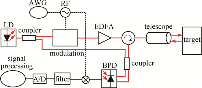
基于外调制的FMCW激光雷达系统组成如图 1所示。
半导体激光器(laser diode, LD)发出的连续波激光经光纤分束器被分成两束,功率较大的为探测光,功率较小的为本振光。探测光作为入射光进入电光调制器,任意波形发生器(arbitrary waveform generator, AWG)发出的调频连续波射频(radio frequency, RF)信号经电光调制器调制到入射光上,经掺铒光纤放大器(erbium-doped fiber amplifier, EDFA)放大,再经环形器、准直器准直后发射到空间中。发射光从待测目标处返回的回波信号与本振信号经过2×2耦合器后一起进入平衡光电探测器(balanced photodetector, BPD),经混频、滤波后提取目标距离信息。以锯齿波形式的RF信号为例,假设其调制带宽为B、周期为T, 信号处理系统在本振信号与回波信号混频并滤去高次谐波分量后经快速傅里叶变换(fast Fourier transform, FFT)提取出中频(intermediate frequency, IF)频率fIF,从而计算出目标与激光雷达系统之间的距离L:
L=fIFTc2B (1) 式中, c为光速。由FFT得到的矩形窗频谱能分辨的最小频率间隔为1/T,即ΔfIF=1/T,将其代入(1)式可得FMCW激光雷达系统的距离分辨率:
ΔL=c2B (2) (2) 式说明系统的探测距离分辨率只与射频信号的调制带宽有关。
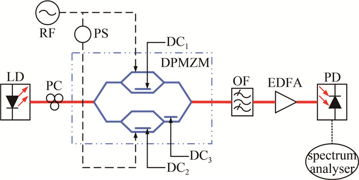
微波光子倍频技术是产生大带宽信号的一种方法,图 2展示了其系统组成。激光器产生单频连续波激光,经偏振控制器(polarization controller, PC)进入调制器。在本文中,调制器为DPMZM,其内部由3个马赫-曾德尔结构组成,分别为两个子MZM(MZM1和MZM2)和一个主MZM(MZM3),子MZM位于主MZM的两个调制臂上。RF信号经电移相器(phase shifter, PS)加载到DPMZM的调制臂上,对光信号进行调制,产生多频率的光谐波分量。通过控制调制器的直流偏置电压、调制系数等参数,或使用光学滤波器(optical filter, OF)等元件,可实现对载波和不需要的低阶边带的抑制。最后,经EDFA放大后在光电探测器(photodetector, PD)中进行平方律检测可以得到倍频信号。通过频谱分析仪可对倍频后的信号进行观察。
为不失一般性,假设单频连续波激光的光场初相位为0,光场强度为E0,载波频率为ωc,t为持续时间,则激光器的出射信号Ein(t)可表示为:
Ein (t)=E0exp(iωct) (3) DPMZM的半波电压为Vπ,分光比为γ。分光比γ由消光比确定,理想情况下消光比无穷大,则γ=0.5。假设射频调制信号幅度为VRF,调制频率为ωm,电移相器产生的相移为φ,则MZM1和MZM2两臂上加载射频调制信号分别表示为:
VRF1(t)=VRFcos(ωmt) (4) VRF2(t)=−VRFcos(ωmt) (5) VRF3(t)=VRFcos(ωmt+φ) (6) VRF4(t)=−VRFcos(ωmt+φ) (7) 3个调制臂上分别加载直流(direct-current, DC)偏置电压VDC1、VDC2、VDC3,则两个子MZM和主MZM的输出光场分别为:
\begin{array}{c} E_{\mathrm{MZM}_1}(t)=\sqrt{\gamma} E_0 \exp \left(\mathrm{i} \omega_{\mathrm{c}} t\right)\left\{\gamma \exp \left\{\mathrm{i} {\rm{ \mathsf{ π} }}\left[\frac{V_{\mathrm{RF}} \cos \left(\omega_{\mathrm{m}} t\right)}{V_{\rm{ \mathsf{ π} }}}\right]\right\}+\right. \\ \left.(1-\gamma) \exp \left\{\mathrm{i} {\rm{ \mathsf{ π} }}\left[\frac{V_{\mathrm{DC}_1}}{V_{\rm{ \mathsf{ π} }}}-\frac{V_{\mathrm{RF}} \cos \left(\omega_{\mathrm{m}} t\right)}{V_{\rm{ \mathsf{ π} }}}\right]\right\}\right\} \end{array} (8) \begin{gathered} E_{\mathrm{MZM}_2}(t)=\sqrt{1-\gamma} E_0 \exp \left(\mathrm{i} \omega_{\mathrm{c}} t\right) \times \\ \left\{\gamma \exp \left\{\mathrm{i} {\rm{ \mathsf{ π} }}\left[\frac{V_{\mathrm{RF}} \cos \left(\omega_{\mathrm{m}} t+\varphi\right)}{V_{\rm{ \mathsf{ π} }}}\right]\right\}+\right. \\ \left.(1-\gamma) \exp \left\{\mathrm{i} {\rm{ \mathsf{ π} }}\left[\frac{V_{\mathrm{DC}_2}}{V_{\rm{ \mathsf{ π} }}}-\frac{V_{\mathrm{RF}} \cos \left(\omega_{\mathrm{m}} t+\varphi\right)}{V_{\rm{ \mathsf{ π} }}}\right]\right\}\right\} \end{gathered} (9) \begin{gathered} E_{\mathrm{MZM}_3}(t)= \\ \sqrt{\gamma} E_{\mathrm{MZM}_1}+\sqrt{1-\gamma} E_{\mathrm{MZM}_2} \exp \left[\mathrm{i} {\rm{ \mathsf{ π} }}\left(V_{\mathrm{DC}_3} / V_{\rm{ \mathsf{ π} }}\right)\right] \end{gathered} (10) 令φ=π/2,VDC1=VDC2=VDC3=0,则:
\begin{gathered} E_{\mathrm{MZM}_3}(t)=\gamma E_0 \exp \left(\mathrm{i} \omega_{\mathrm{c}} t\right)\left\{\gamma \exp \left\{\mathrm{i} {\rm{ \mathsf{ π} }}\left[\frac{V_{\mathrm{RF}} \cos \left(\omega_{\mathrm{m}} t\right)}{V_{\rm{ \mathsf{ π} }}}\right]\right\}+\right. \\ \left.(1-\gamma) \exp \left\{\mathrm{i} {\rm{ \mathsf{ π} }}\left[-\frac{V_{\mathrm{RF}} \cos \left(\omega_{\mathrm{m}} t\right)}{V_{\rm{ \mathsf{ π} }}}\right]\right\}\right\}+ \\ (1-\gamma) E_0 \exp \left(\mathrm{i} \omega_{\mathrm{c}} t\right)\left\{\gamma \exp \left\{\mathrm{i} {\rm{ \mathsf{ π} }}\left[\frac{V_{\mathrm{RF}} \cos \left(\omega_{\mathrm{m}} t+{\rm{ \mathsf{ π} }} / 2\right)}{V_{\rm{ \mathsf{ π} }}}\right]\right\}+\right. \\ \left.(1-\gamma) \exp \left\{\mathrm{i} {\rm{ \mathsf{ π} }}\left[-\frac{V_{\mathrm{RF}} \cos \left(\omega_{\mathrm{m}} t+{\rm{ \mathsf{ π} }} / 2\right)}{V_{\rm{ \mathsf{ π} }}}\right]\right\}\right\} \end{gathered} (11) 设调制系数β=πVRF/Vπ,则有:
\begin{gathered} E_{\mathrm{MZM}_3}(t)=E_0 \exp \left(\mathrm{i} \omega_{\mathrm{c}} t\right)\left\{\gamma^2 \exp \left[\mathrm{i} \beta \cos \left(\omega_{\mathrm{m}} t\right)\right]+\right. \\ \gamma(1-\gamma) \exp \left[-\mathrm{i} \beta \cos \left(\omega_{\mathrm{m}} t\right)\right]+\gamma(1-\gamma) \times \\ \exp \left[\mathrm{i} \beta \cos \left(\omega_{\mathrm{m}} t+{\rm{ \mathsf{ π} }} / 2\right)\right]+(1-\gamma)^2 \times \\ \left.\exp \left[-\mathrm{i} \beta \cos \left(\omega_{\mathrm{m}} t+{\rm{ \mathsf{ π} }} / 2\right)\right]\right\}= \\ E_0 \exp \left(\mathrm{i} \omega_{\mathrm{c}} t\right)\left\{\gamma^2 \exp \left[\mathrm{i} \beta \cos \left(\omega_{\mathrm{m}} t\right)\right]+\gamma(1-\gamma) \times\right. \\ \exp \left[\mathrm{i} \beta \cos \left(\omega_{\mathrm{m}} t+{\rm{ \mathsf{ π} }}\right)\right]+\gamma(1-\gamma) \exp \left[\mathrm { i } \beta \cos \left(\omega_{\mathrm{m}} t+\right.\right. \\ \left.{\rm{ \mathsf{ π} }} / 2)]+(1-\gamma)^2 \exp \left[\mathrm{i} \beta \cos \left(\omega_{\mathrm{m}} t-{\rm{ \mathsf{ π} }} / 2\right)\right]\right\} \end{gathered} (12) 根据Jacobi-Anger展开式,上式可写成:
\begin{gathered} E_{\mathrm{MZM}_3}(t)=E_0 \exp \left(\mathrm{i} \omega_{\mathrm{c}} t\right)\left\{\sum\limits_{n=-\infty}^{+\infty} \mathrm{i}^n \mathrm{~J}_n(\beta) \exp \left(\mathrm{i} n \omega_{\mathrm{m}} t\right) \times\right. \\ {\left[\gamma^2+\gamma(1-\gamma) \exp (\mathrm{i} n {\rm{ \mathsf{ π} }})+\gamma(1-\gamma) \times\right.} \\ \left.\left.\exp (\mathrm{i} n {\rm{ \mathsf{ π} }} / 2)+(1-\gamma)^2 \exp (-\mathrm{i} n {\rm{ \mathsf{ π} }} / 2)\right]\right\} \end{gathered} (13) 式中,Jn(·)为第1类第n阶贝塞尔函数。理想情况下取γ=0.5, 则:
\begin{gathered} E_{\mathrm{MZM}_3}(t)=\frac{1}{4} E_0 \exp \left(\mathrm{i} \omega_{\mathrm{c}} t\right)\left\{\sum\limits_{n=-\infty}^{+\infty} \mathrm{i}^n \mathrm{J}_n(\beta) \exp \left(\mathrm{i} n \omega_{\mathrm{m}} t\right) \times\right. \\ \left.\left[1+\exp (\mathrm{i} n {\rm{ \mathsf{ π} }})\right]\left[1+\exp (-\mathrm{i} n {\rm{ \mathsf{ π} }} / 2)\right]\right\} \end{gathered} (14) 根据Bessel函数的特性,5阶以上的边带功率很小,可以将其忽略,所以上式展开为:
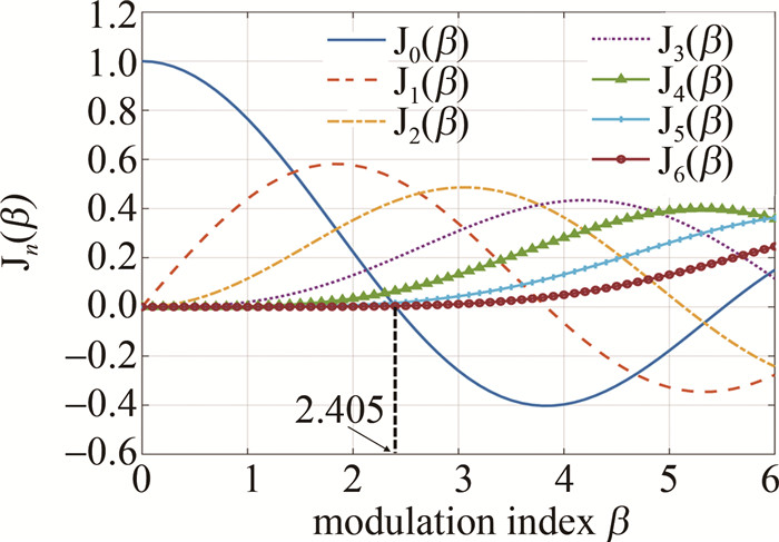
\begin{gathered} E_{\mathrm{MZM}_3}(t) \approx E_0 \exp \left(\mathrm{i} \omega_{\mathrm{c}} t\right)\left\{\mathrm{J}_0(\beta)+\right. \\ \left.\mathrm{J}_4(\beta)\left[\exp \left(\mathrm{i} 4 \omega_{\mathrm{m}} t\right)+\exp \left(-\mathrm{i} 4 \omega_{\mathrm{m}} t\right)\right]\right\} \end{gathered} (15) 如图 3所示,当调制系数β≈2.405时,J0(β)=0,输出端光信号主要为±4边带。经响应度为R的光电探测器后,输出的光电流iph(t)与输入光功率的平方成正比:
i_{\mathrm{ph}}(t) \propto R E_{\mathrm{MZM}_3} E_{\mathrm{MZM}_3}\text{ }^* \propto R J_4^2(\beta) \cos \left(8 \omega_{\mathrm{m}} t\right) (16) 式中,上标*表示复共轭。此方法无需光滤波器即得到了8倍于射频信号频率的倍频信号,信号的带宽B也扩展到原射频信号的8倍,可以满足FMCW激光雷达的大带宽需求。
2. 分析与讨论
2.1 八倍频FMCW激光雷达
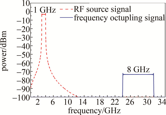
连续波激光器工作在1550 nm。理想情况下,调制器的分光比γ=0.5,产生的射频源信号和八倍频宽带射频调制信号如图 4所示。
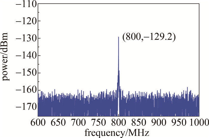
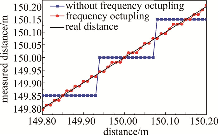
将倍频后的信号用于FMCW激光雷达,设置目标距离为150 m,获得图 5所示的探测信号,与未经倍频的初始情况下获得的探测信号相比,信号峰所在的频率值变成了8倍,与原理公式的计算结果相符。同时,由于探测信号的峰值功率大大降低,需要灵敏的探测器进行接收。此外,根据仿真模型的探测信号峰所在的频率值对不同距离下的测量值进行了计算,结果如图 6所示。可以看出,八倍频激光雷达将距离分辨率从0.15 m提高到了0.01875 m,与原理计算结果一致。
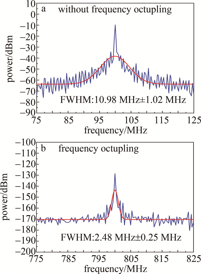
采用Guassian模型分别对未经倍频和八倍频FMCW激光雷达的信号频谱进行单峰拟合,拟合得到的半峰全宽(full width at half maximum, FWHM)值如图 7a和图 7b所示。可以看出,经过倍频后激光雷达的探测信号峰明显变窄,FWHM约为未经倍频时的1/4。
2.2 消光比对倍频激光雷达的影响
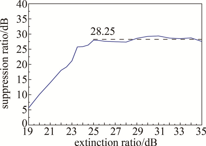
由于受环境温度和材料加工工艺等影响,现实中调制器的消光比不是无穷大。在不同消光比情况下对探测信号峰的功率抑制比进行了分析。仿真结果显示,在19 dB~35 dB的消光比范围内信号的峰值功率稳定在-129.5 dBm~-127.9 dBm之间,考虑到存在随机噪声等因素,可以认为消光比对信号峰值功率没有影响。图 8显示了信号峰功率抑制比随消光比的变化规律。从图中可以看出, 当消光比大于25 dB时,抑制比保持在28.25 dB左右,目前市场上商用调制器大多可以实现30 dB以上的消光比,可以满足倍频激光雷达的使用需求。
2.3 调制系数对倍频激光雷达的影响
为了最大化地抑制其它边带,调制系数β≈2.405。相应地,根据公式得射频调制信号驱动电压VRF为:
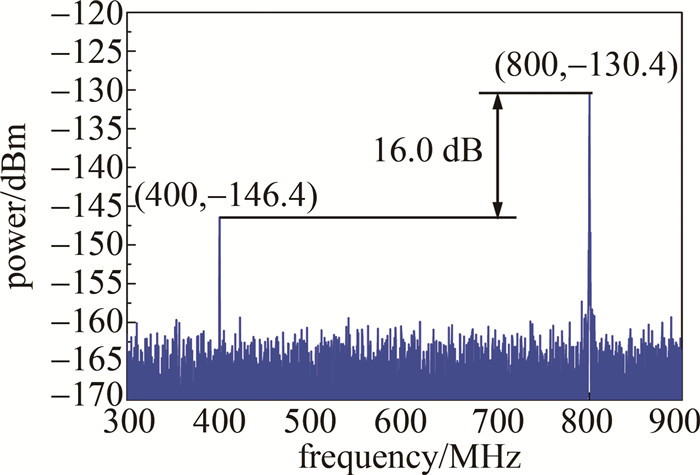
V_{\mathrm{RF}}=\frac{\beta V_{\rm{ \mathsf{ π} }}}{{\rm{ \mathsf{ π} }}} \approx \frac{2.405 \times 4}{{\rm{ \mathsf{ π} }}} \approx 3.062 \mathrm{~V} (17) 若电压存在误差,以VRF=3.032 V即β≈2.381时为例,低阶边带的拍频使得产生的八倍频信号中含有四倍频信号,相应地在图 9中激光雷达探测信号的400 MHz处存在另一个峰,它与800 MHz处峰的抑制比为-16.0 dB。
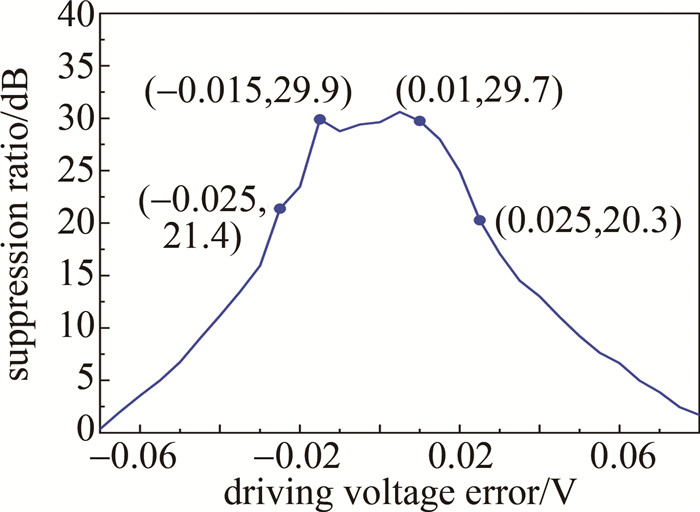
通过图 10中激光雷达探测信号峰的功率抑制比随射频调制信号的驱动电压误差的变化关系可以看出,在-0.015 V~+0.01 V范围内,信号峰功率抑制比保持在28.5 dB以上,考虑噪声等随机误差因素,可以认为它的变化很小。在±0.025 V的变化范围内,对应调制系数β为2.385~2.425,信号峰的功率抑制比始终保持在20 dB以上,即此范围内的电压误差可以被系统接受,目前市面上商用任意波形发生器可以满足该需求。
2.4 相位误差对倍频激光雷达的影响
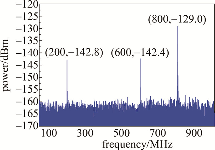
电移相器的相位误差同样会导致产生的倍频信号存在其它边带。以φ=88°时为例,倍频信号中除八倍频外还含有二倍频、四倍频和六倍频分量,相应地在图 11中激光雷达探测信号的200 MHz和600 MHz处产生了两个峰。
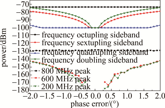
图 12中展示了电移相器的相位误差在±2°范围内时倍频信号中八倍频、六倍频、四倍频和二倍频边带的功率,以及激光雷达探测信号中位于200 MHz、600 MHz和800 MHz处3个峰的峰值。在图中所示的相位误差范围内,八倍频边带的功率和对应产生在800 MHz处峰的峰值基本不变。随着相位逐渐偏离90°,倍频信号中六倍频边带和二倍频边带的功率逐渐升高,且二倍频边带的功率更高,但两个边带对应在600 MHz和200 MHz处两个峰的峰值相差不大。在图中±0.3°以外的范围内,随着相位越来越偏离90°, 600 MHz和200 MHz处两个峰的功率越来越高,但在±0.3°范围内,两处没有明显突出的峰值。当相位偏移超过±1.6°时,倍频信号中才有四倍频分量出现,由于功率很小,在400 MHz处没有出现明显的峰。
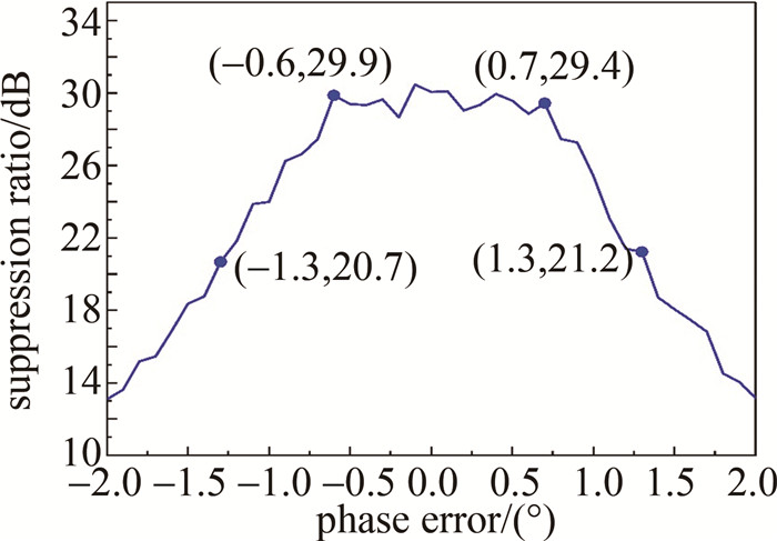
探测信号峰的功率抑制比随电移相器相位误差的变化情况如图 13所示。在-0.6°~+0.7°范围内,抑制比保持在28.5 dB以上,考虑噪声等随机误差因素,可以认为这一变化很小。在±1.3°的变化范围内,信号峰的功率抑制比始终保持在20 dB以上,即±1.3°的电移相器误差是可以被系统接受的。
3. 结论
基于DPMZM的微波光子倍频方法结构简单、容易调试、相位噪声低且稳定性好,可结合外调制技术实现对FMCW激光雷达带宽限制的突破。本文作者通过在模拟环境中进行仿真实验平台的搭建,证明了采用无光滤波器的微波光子倍频技术可以将1 GHz的射频源倍频生成8 GHz的宽带射频调制信号,通过带宽的提高实现FMCW激光雷达的高距离分辨率。通过分析倍频子系统中DPMZM的消光比、信号发生器的驱动电压以及电移相器的相位对激光雷达探测性能的影响,发现当调制器的消光比大于25 dB时,FMCW激光雷达探测信号峰的功率抑制比即稳定在28.25 dB左右。此外,当调制系数在2.385~2.425范围内或电移相器误差不大于1.3°时,探测信号峰的功率抑制比可以保持在20 dB以上。因此,目前市面上的相关商用器件可以满足基于微波光子倍频的FMCW激光雷达的探测指标需求,即可通过低成本方法实现高带宽FMCW激光雷达。
-
-
[1] 李超林, 刘俊辰, 张福民, 等. 频率调制连续波激光雷达测量技术的非线性校正综述[J]. 光电工程, 2022, 49(7): 210438. https://www.cnki.com.cn/Article/CJFDTOTAL-GDGC202207006.htm LI Ch L, LIU J Ch, ZHANG F M, et al. Review of nonlinearity co-rrection of frequency modulated continuous wave LiDAR measurement technology[J]. Opto-Electron Engineering, 2022, 49(7): 210438(in Chinese). https://www.cnki.com.cn/Article/CJFDTOTAL-GDGC202207006.htm
[2] BEHROOZPOUR B, SANDBORN P A M, WU M C, et al. LiDAR system architectures and circuits[J]. IEEE Communications Magazine, 2017, 55(10): 135-142. DOI: 10.1109/MCOM.2017.1700030
[3] ROYO S, BALLESTA-GARCIA M. An overview of LiDAR imaging systems for autonomous vehicles[J]. Applied Sciences, 2019, 9(19): 4093. DOI: 10.3390/app9194093
[4] SCHWARZ B. LiDAR: Mapping the world in 3D[J]. Nature Photonics, 2010, 4(7): 429-430. DOI: 10.1038/nphoton.2010.148
[5] MITCHELL E W, HOEHLER M S, GIORGETTA F R, et al. Cohe-rent laser ranging for precision imaging through flames[J]. Optica, 2018, 5(8): 988-995. DOI: 10.1364/OPTICA.5.000988
[6] DILAZARO T, NEHMETALLAH G. Large-volume, low-cost, high-precision FMCW tomography using stitched DFBs[J]. Optics Express, 2018, 26(3): 2891-2904. DOI: 10.1364/OE.26.002891
[7] POULTON C V, YAACOBI A, COLE D B, et al. Coherent solid-state LiDAR with silicon photonic optical phased arrays[J]. Optics Letters, 2017, 42(20): 4091-4094. DOI: 10.1364/OL.42.004091
[8] LI G Z, WANG R, SONG Z Q, et al. Linear frequency-modulated continuous-wave ladar system for synthetic aperture imaging[J]. A-pplied Optics, 2017, 56: 3257-3262.
[9] GAO S, HUI R. Frequency-modulated continuous-wave LiDAR using I/Q modulator for simplified heterodyne detection[J]. Optics Letters, 2012, 37(11): 2022-2024. DOI: 10.1364/OL.37.002022
[10] XU Zh Y, ZHANG H, CHEN K, et al. FMCW LiDAR using phase-diversity coherent detection to avoid signal aliasing[J]. IEEE Photonics Technology Letters, 2019, 31(22): 1822-1825. DOI: 10.1109/LPT.2019.2948471
[11] ZHANG T, QU X H, ZHANG F M. Nonlinear error correction for FMCW ladar by the amplitude modulation method[J]. Optics Express, 2018, 26(9): 11519-11528. DOI: 10.1364/OE.26.011519
[12] ALAVI S E, SOLTANIAN M R K, AMIRI I S, et al. Towards 5G: A photonic based millimeter wave signal generation for applying in 5G access fronthaul[J]. Scientific Reports, 2016, 6: 19891. DOI: 10.1038/srep19891
[13] MATSKO A. Advances in the development of spectrally pure microwave photonic synthesizers[J]. IEEE Photonics Technology Letters, 2019, 31(23): 1882-1885. DOI: 10.1109/LPT.2019.2947901
[14] YAO J P, CAPMANY J. Microwave photonics[J]. Science China Information Sciences, 2022, 65: 221401. DOI: 10.1007/s11432-021-3524-0
[15] DEGLI-EREDI I, AN P L, DRASBAEK J, et al. Millimeter-wave generation using hybrid silicon photonics[J]. Journal of Optics, 2021, 23(4): 043001. DOI: 10.1088/2040-8986/abc312
[16] HOANG V N. A cost-effective DD-OFDM ROF system employing FBG and DML to generate optical mm-wave[J]. Journal of Optical Communications, 2014, 35(2): 141-149.
[17] WANG Y Y, YANG Ch, CHI N, et al. Photonic frequency-quadrupling and balanced pre-coding technologies for W-band QPSK vector mm-wave signal generation based on a single DML[J]. Optics Communications, 2016, 367: 239-243. DOI: 10.1016/j.optcom.2016.01.058
[18] KURI T, KITAYAMA K. Laser phase noise free optical heterodyne detection technique for 60-GHz-band radio-on-fiber systems[C]// International Topical Meeting on Microwave Photonics. New York, USA: IEEE, 2000: 141-144.
[19] LI J, NING T G, PEI L, et al. 60 GHz millimeter-wave generator based on a frequency-quadrupling feed-forward modulation technique[J]. Optics Letters, 2010, 35(21): 3619-3621. DOI: 10.1364/OL.35.003619
[20] CARPINTERO G, BALAKIER K, YANG Z, et al. Microwave photonic integrated circuits for millimeter-wave wireless communications[J]. Journal of Lightwave Technology, 2014, 32(20): 3495-3501. DOI: 10.1109/JLT.2014.2321573
[21] XIAO J N, ZHANG Z R, LI X Y, et al. High-frequency photonic vector signal generation employing a single phase modulator[J]. IEEE Photonics Journal, 2015, 7(2): 1-6.
[22] WU Z Y, Cao Ch Q, ZENG X D, et al. Filterless radio-over-fiber system to generate 40 and 80 GHz millimeter-wave[J]. IEEE Photonics Journal, 2020, 12(6): 1-13.
[23] SHIH P T, CHEN J, LIN C T, et al. Optical millimeter-wave signal generation via frequency 12-tupling[J]. Journal of Lightwave Technology, 2009, 28(1): 71-78.
[24] ZHANG Ch F, WANG L Y, QIU K. Proposal for all-optical generation of multiple-frequency millimeter-wave signals for RoF system with multiple base stations using FWM in SOA[J]. Optics Express, 2011, 19(15): 13957-13962. DOI: 10.1364/OE.19.013957
[25] PARK C S, LEE C G, PARK C S. Photonic frequency upconversion by SBS-based frequency tripling[J]. Journal of Lightwave Technology, 2007, 25(7): 1711-1718. DOI: 10.1109/JLT.2007.897749
[26] KUMARI A, KUMAR A, GAUTAM A. Photonic generation and theoretical investigation of phase noise in quadrupling and 12-tupling millimeter wave signal using optical self-heterodyne system[J]. Optik—International Journal for Light and Electron Optics, 2021, 231(7): 166432.
[27] PREM P K A, CHAKRAPANI A. A millimeter-wave generation scheme based on frequency octupling using LiNbO3 Mach-Zehnder modulator[J]. National Academy Science Letters, 2019, 42: 401-406. DOI: 10.1007/s40009-018-0766-3
[28] LI X, ZHAO Sh H, ZHU Z H, et al. An optical millimeter-wave generation scheme based on two parallel dual-parallel Mach-Zehnder modulators and polarization multiplexing[J]. Journal of Modern Optics, 2015, 62(18): 1502-1509. DOI: 10.1080/09500340.2015.1045948
[29] ZHU Z H, ZHAO Sh H, CHU X Ch, et al. Optical generation of millimeter-wave signals via frequency 16-tupling without an optical filter[J]. Optics Communications, 2015, 354: 40-47. DOI: 10.1016/j.optcom.2015.05.035
[30] CHOI S T, YANG K S, NISHI S, et al. A 60-GHz point-to-multipoint millimeter-wave fiber-radio communication system[J]. IEEE Transactions on Microwave Theory & Techniques, 2006, 54(5): 1953-1960.
[31] OH T K, KIM H J, LEE S H, et al. Photonic frequency quadrupling utilizing a LiNbO3 phase modulator and a Brillouin-assisted optical filter[C]// 2011 International Topical Meeting on Microwave Photonics Jointly Held with the 2011 Asia-Pacific Microwave Photonics Conference. New York, USA: IEEE, 2011: 195-197.
[32] CHAUDHURI R B, BARMAN A D, BOGONI A. Photonic 60 GHz sub-bands generation with 24-tupled frequency multiplication using cascaded dual parallel polarization modulators[J]. Optical Fiber Technology, 2020, 58: 102244. DOI: 10.1016/j.yofte.2020.102244
[33] BASKARAN M, PRABAKARAN R, GAYATHRI T S. Photonic generation of frequency 16-tupling millimeter wave signal using polarization property without an optical filter[J]. Optik—International Journal for Light and Electron Optics, 2019, 184(9): 348-355.
[34] CHEN Y, WEN A J, SHANG L. Analysis of an optical mm-wave generation scheme with frequency octupling using two cascaded Mach-Zehnder modulators[J]. Optics Communications, 2010, 283(24): 4933-4941. DOI: 10.1016/j.optcom.2010.07.046
[35] 王天亮, 袁牧野, 刘波, 等. 基于微波光子学的倍频三角波生成方法[J]. 激光技术, 2019, 43(1): 79-82. DOI: 10.7510/jgjs.issn.1001-3806.2019.01.016 WANG T L, YUAN M Y, LIU B, et al. Triangular waveform generation with frequency doubling based on microwave photonics[J]. Laser Technology, 2019, 43(1): 79-82(in Chinese). DOI: 10.7510/jgjs.issn.1001-3806.2019.01.016
[36] RANI A, KEDIA D. Filterless millimeter-wave generation with tunable tupling factors using dual parallel-MZMs[C]//2021 4th International Conference on Recent Trends in Computer Science and Technology (ICRTCST). New York, USA: IEEE, 2022: 135-141.
-
期刊类型引用(1)
1. 胡申博,刘俊辰,余苏,杨承昱,曲兴华,张福民. 调频连续波激光多路并行相干精密长度测量方法. 光电工程. 2024(03): 107-116 .  百度学术
百度学术
其他类型引用(1)


 下载:
下载:
